Texas Flying Legends
by Chuck Cravens
![]()
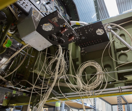
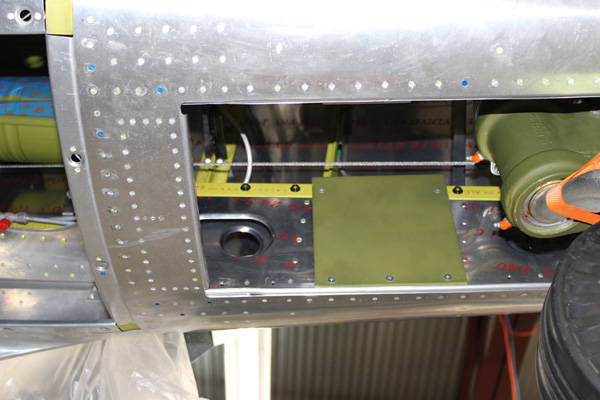
An angle from below gives us a different perspective on the electrical work.
Update
Last month’s cover showed Aaron making up wiring harnesses and inside were other photos of him wiring up the pilot’s main switch box. This month those harnesses were put to use as Aaron began the meticulous and exacting job of wiring the Mustang’s cockpit.
Wiring
The wire used for this restoration is identical to that used for one of our previous Mustang, Sierra Sue II. Both Mustangs were actually produced the same year, even though the serial numbers begin one year apart. I described the wire in my book on that restoration as follows:
Properly restoring the wiring in the airframe required duplicating wire used in 1944. The wire used then was insulated with black rubber and wound with cotton string. It was then lacquered and a logo applied. Like anything else, the current generation of available wiring is differently made and labeled. To be true as possible to 1944, wire with black silicon insulation was custom-made by Allied Wire and cable of Pewaukee, Wisconsin. Ordinary rubber insulation is no longer allowed by FAA specifications. The custom wire was then wrapped with cotton string like the original stuff by Narragansett Reproductions of Wood River Junction, Rhode Island.
Erik Trueblood at AirCorps Aviation researched the logo right down to the exact font used back then. A period Kingsley wire stamping machine was found complete with several type cases containing different sizes of the correct period type. Different sizes were used on different wire gauges.1
1. Chuck Cravens Combat Vet P-51, the History of Sierra Sue II, World War Two Survivor, (Edina, Minnesota, Beaver’s Pond Press, 2015), 69
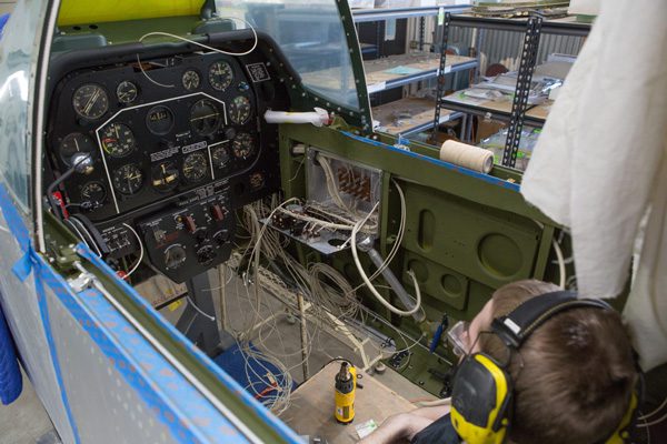
Aaron is looking over the job ahead of him. The yellow object in front of Aaron is a heat gun.
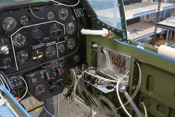
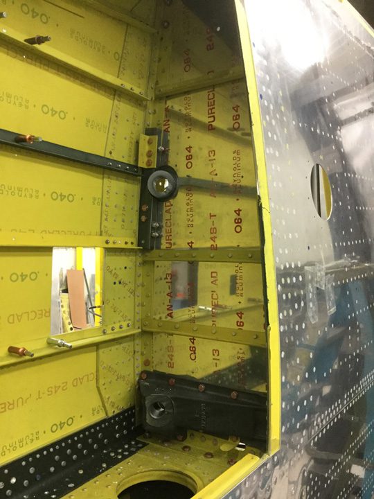
The view of the right hand side of the cockpit shows the circuit breaker box opened up. The mask we show being made later in the report is for this box.
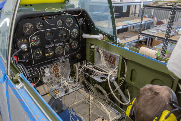
Here the pilot’s main switch box is open as well.
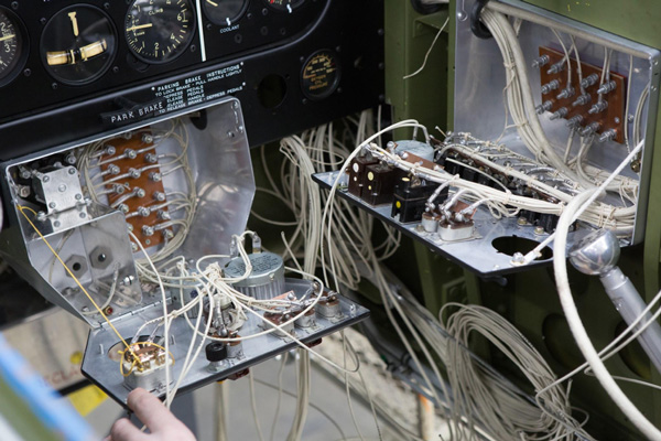
This tight view lets us see the many connections that have to be neatly and securely made in just these two boxes in order to have a reliable electrical system.
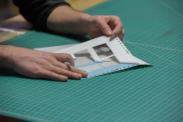
Art
The various electrical components need art and graphics work to be accurate.
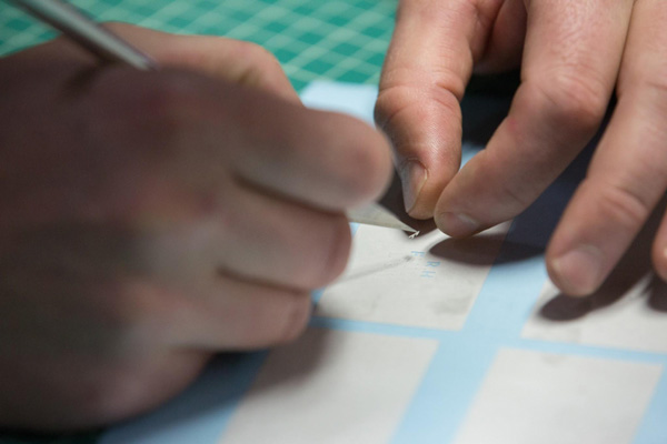
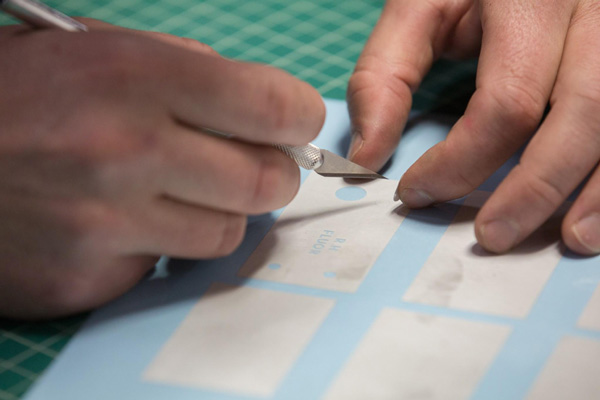
In this case it says “RH FLOUR.” And the word “LIGHT” will be unmasked as well. It stands for “right hand flourescent light” and is a label on the circuit breaker box cover on the right side of the cockpit. It identifies a rheostat that controls the intensity of ultraviolet cockpit interior lighting.
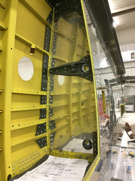
Here is a view up through the tail wheel bay.
You can see the rudder control cable alongside and above the large tail wheel casting. The two small orange projections from the green casting are Zerk fittings painted orange. North American did this to help crewmen find the fittings and to help avoid missing individual grease fittings as the P-51s were serviced in the field.
The main gear are actually the second set we have made for Lope’s Hope 3rd. The first set were pressed into service when Little Horse, a P-51D also owned by Texas Flying Legends Museum, was being serviced at AirCorps. Inspection showed a crack in the pivot shaft and some wear issues. Little Horse flew out with nicely restored gear that day and left the ones removed from her at our hangar.
Since P-51C and D model main gear are interchangeable and both Mustangs have the same owner, we began restoring the former Little Horse gear for Lope’s Hope 3rd.
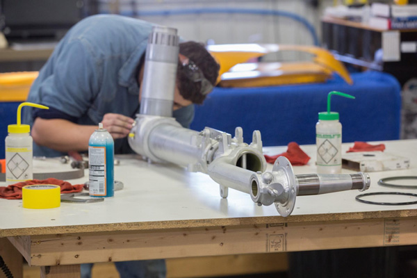
Clyde works on the pivot end of the main gear.
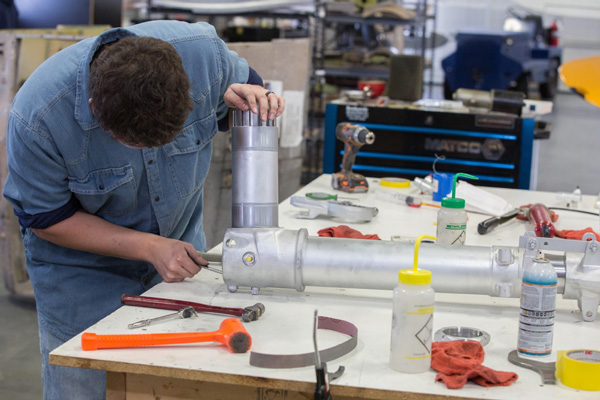
Clyde tightens a bolt on the pivot shaft end of the main gear.
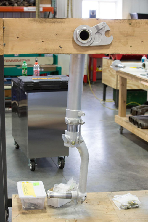
This view shows one completed gear leg.
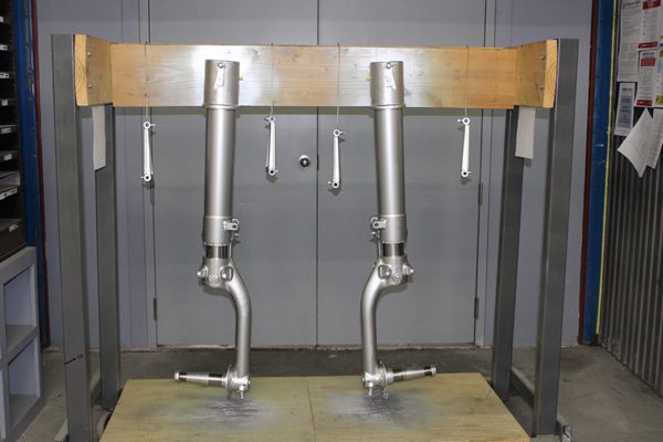
Both gear and the scissors linkages, shown just after painting, hang on a rack in the restoration shop.
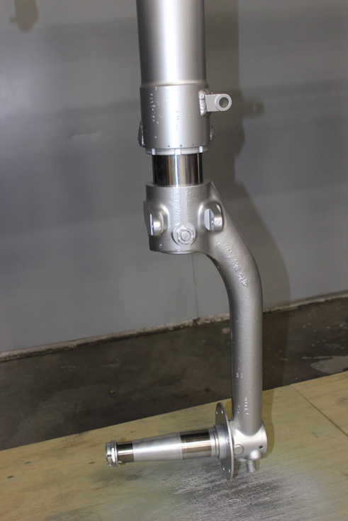
This image shows detail of the gear fork.
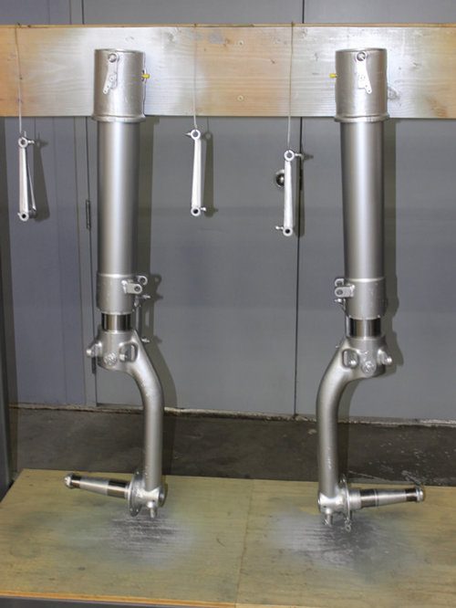
A tight view of the two main gear legs on their paint rack shows more detail.
Wings
The wings for Lope’s Hope 3rd are nearing completion at Odegaard wings.
The parts of the wing assembly remaining to be finished are: assembling the Station 0 rib, the spade doors, and finish the gun bay ribs installation. Then the wings will be removed from the jig, the two halves bolted together, and the flaps, ailerons and wing tips will be fitted.
Once those tasks are completed, the joined wings will be shipped by truck to AirCorps and mated with the fuselage.
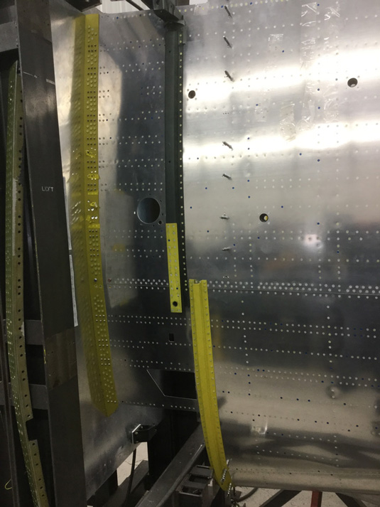
Colin has the wing extension panels completed and he is now drilling mounting holes to size.
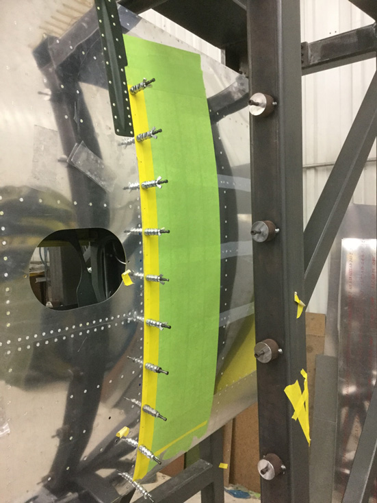
The Station 75 rib has gun mount fittings installed in the right hand wing.
The left side is also fitted but needs to be drilled to size and installed.
The guys are installing the wing fairing nutplates, and the wing attach angles are about 95% installed.