Texas Flying Legends’ Museum
by Chuck Cravens

Update
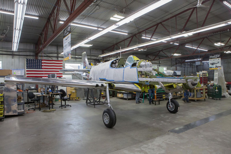
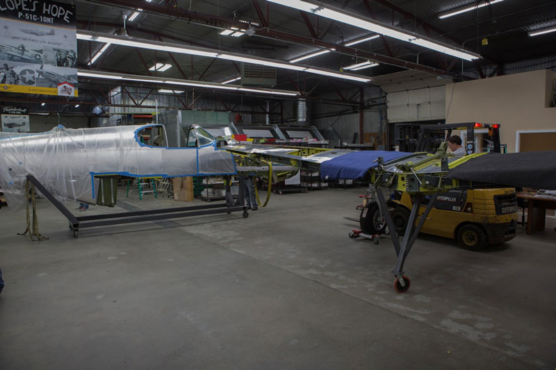
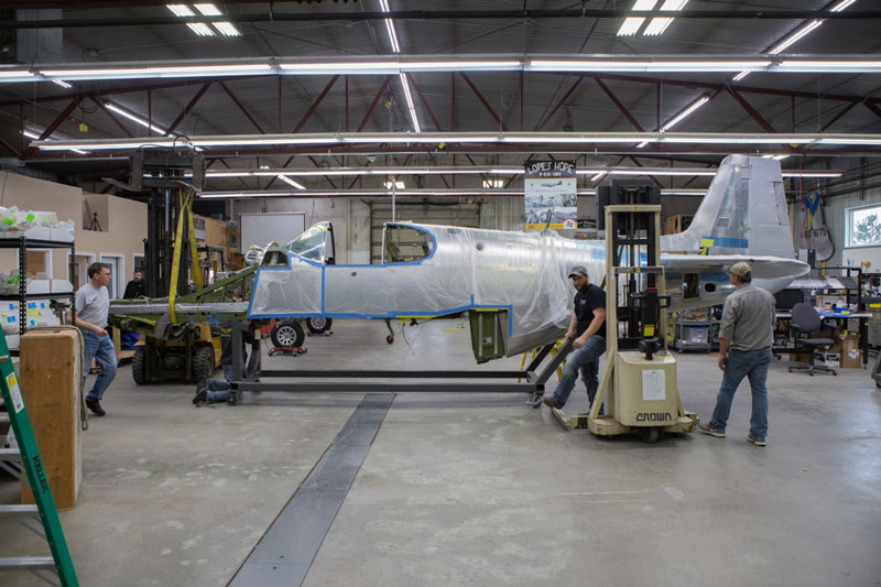
It is an exciting time in the restoration of Lope’s Hope 3rd. As we showed in the last update, the wings have arrived. The wings and fuselage were joined this month to finalize all the fitting. After mating the two major assemblies, many control runs, plumbing, and hydraulic lines were run in order to prepare to separate the wing and fuselage and truck them to the hangar for the final assembly later on.
Mounting the Fuselage on the Wing
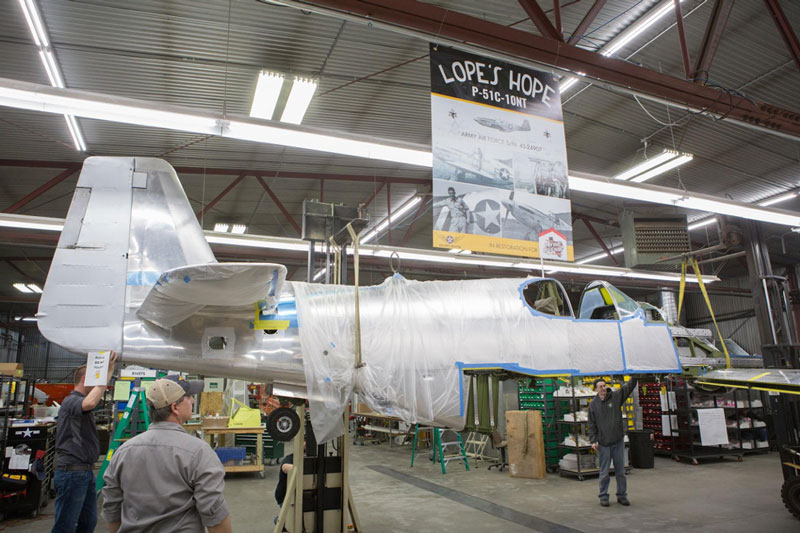
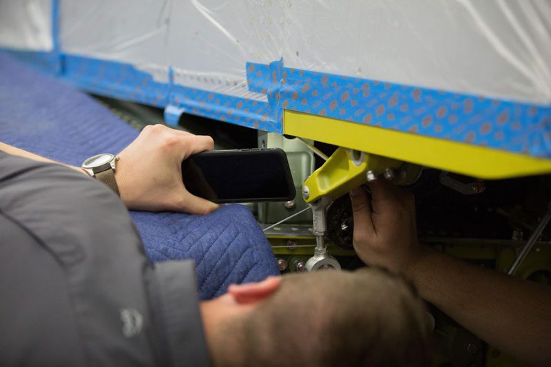
Erik photographs one of the four main wing mounts.
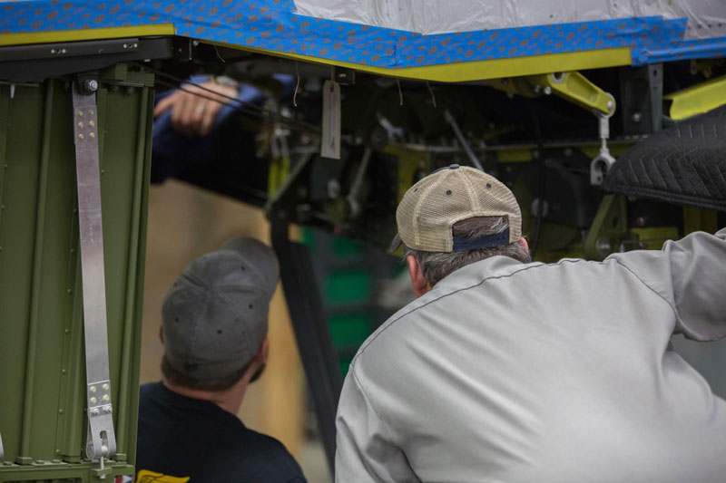
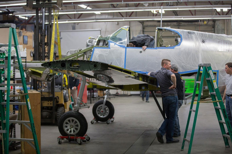
Tye and Robb examine the fit of the wing mounts and prepare to remove the stand.
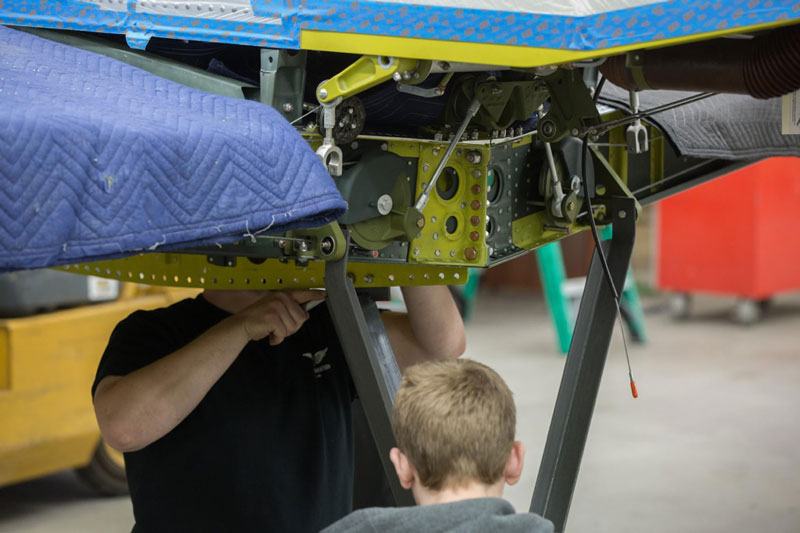
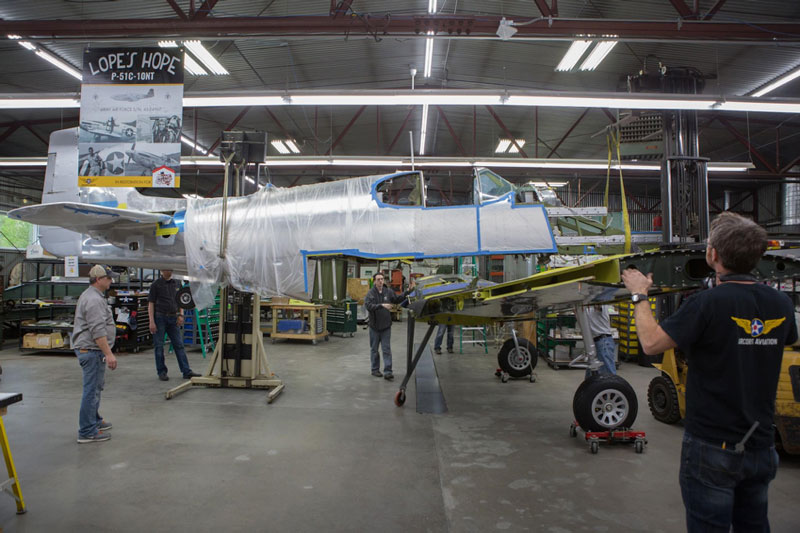
Randy and Aaron remove the wing stand fixture.
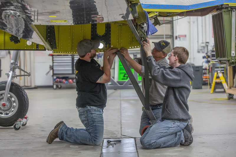
This side view shows Tye, Robb and Aaron working on removal of the wing stand fixture.
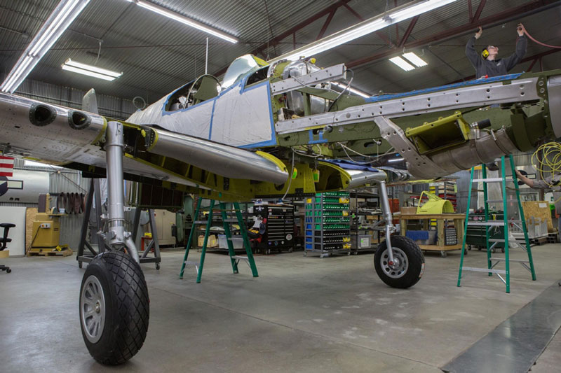
The fuselage is sitting proudly on the wing, with no outside support.
Work on the Controls, Plumbing, and Wiring
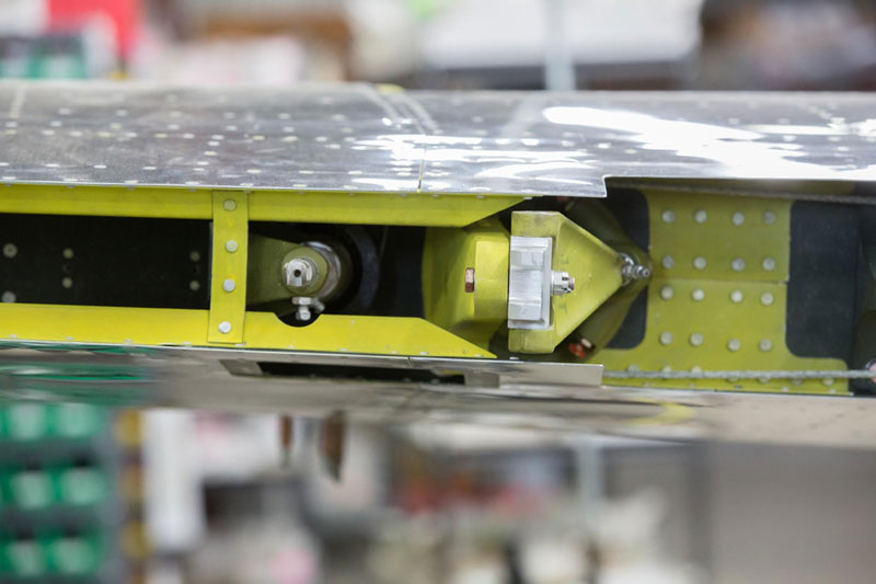
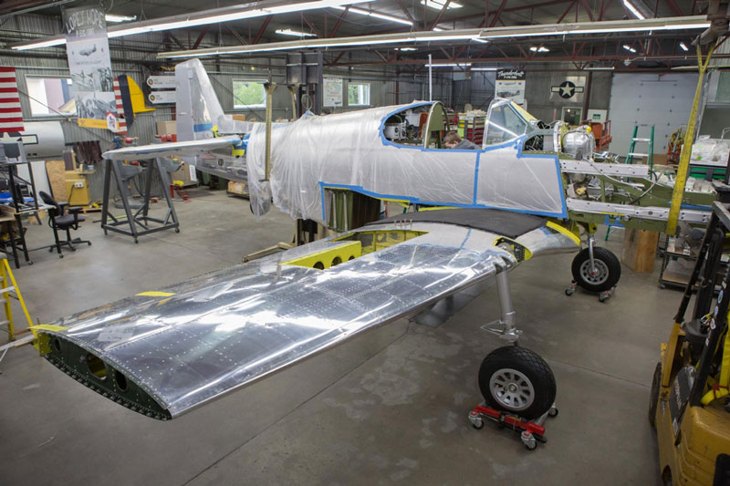
Here is an interesting position on the wing. To the right in the image, the trailing edge is notched more deeply. That would be where the flaps install. Just outboard of that, to the left, is the aileron actuator and the hinge point. The next linkage left of that is the trim tab actuating linkage.
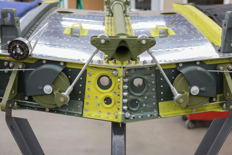
Control stick torque tube connection to the cable system driving the ailerons shows clearly in this image.
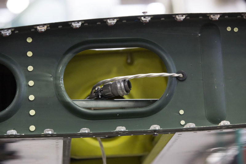
This is an electrical wiring harness for the remote compass, which is located in a small box in the left wing.
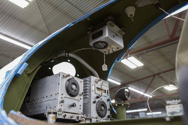
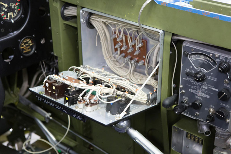
Behind the pilot’s seat is the period correct radio installation. At the top is the communications relay box which connects to the comm antenna.
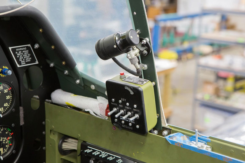
The recognition light switch box mounts on the right side of the cockpit. The switch labeled white controls a white light atop the radio antenna, the red, green, and amber labeled switches control the identification lights below the right wingtip extension.
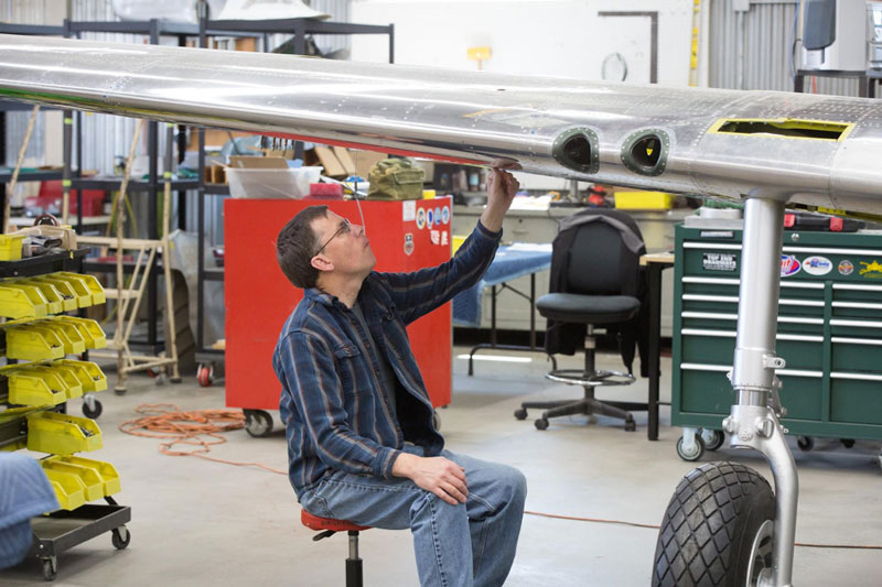
Recognition lights will go in these holes under the right side wing extension. A red lens goes in front, green center, and amber to the rear.
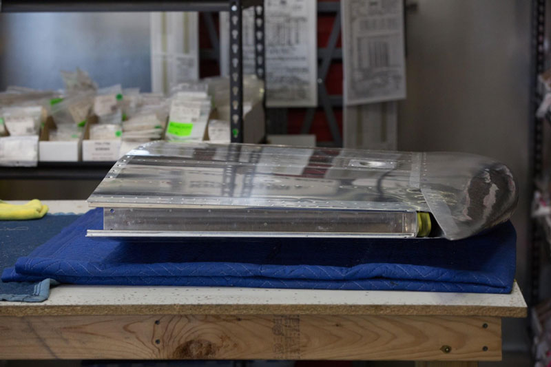
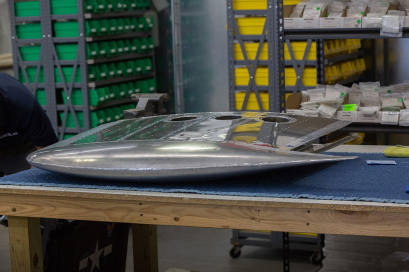
This is a rear view of the left wing extension
The pilot’s main switch box on the the right side is about ready to close up.
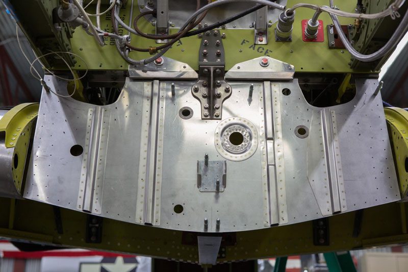
The lower firewall is bolted to both the fuselage and the wing.
The lower firewall is bolted to both the fuselage and the wing.
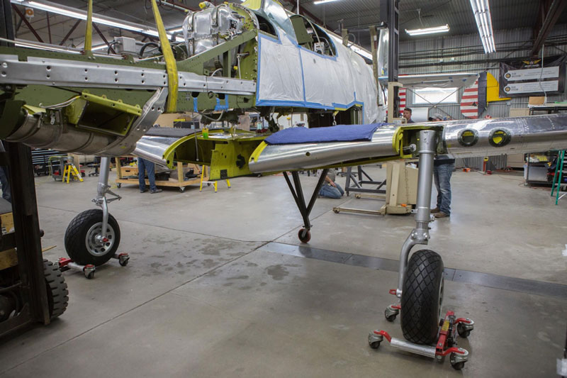
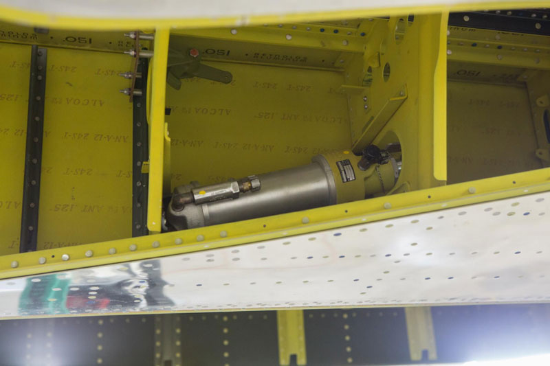
Mark examines the jack point. Here another difference between the B and C models and the later Ds is visible. The photo shows the two gun ports in each wing of the C model instead of the more familiar P-51Ds with three guns in each wing.
Polishing, Fairings, and Skin Work
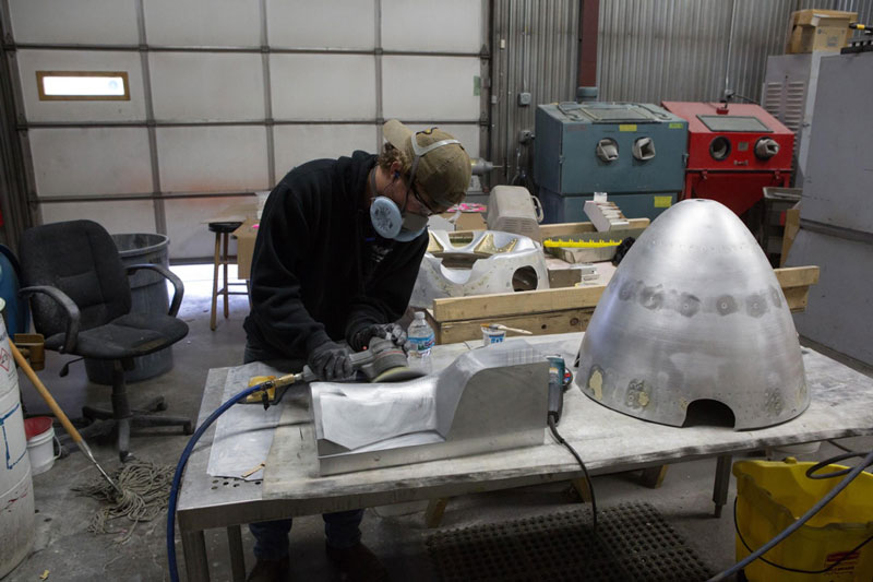
Lope’s Hope 3rd’s spinner will be polished, but in this picture, Alex is polishing a stamping die for a stabilizer fairing.
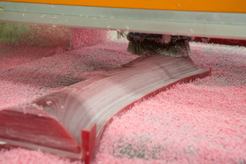
The fab shop is milling the form for the horizontal to fuselage fairing skin.
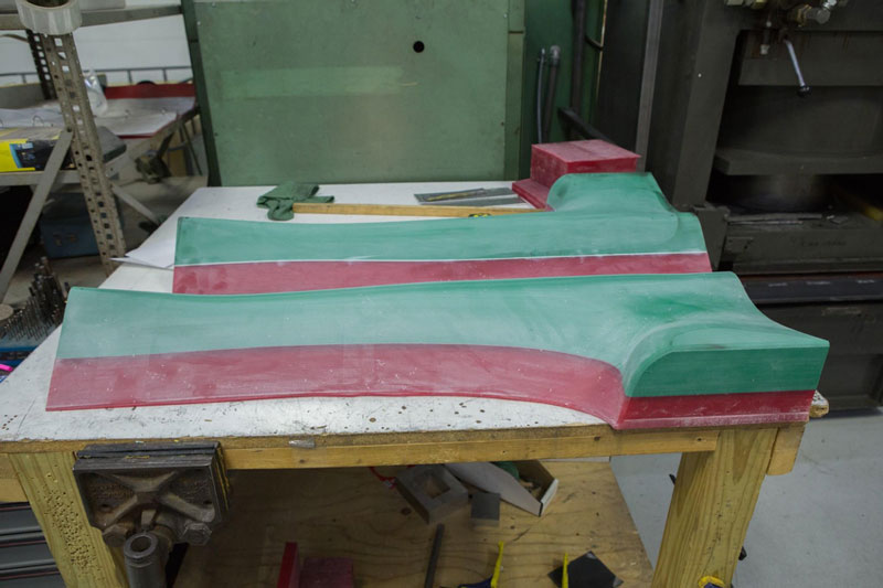
The completed REN plastic forms sit on a bench.
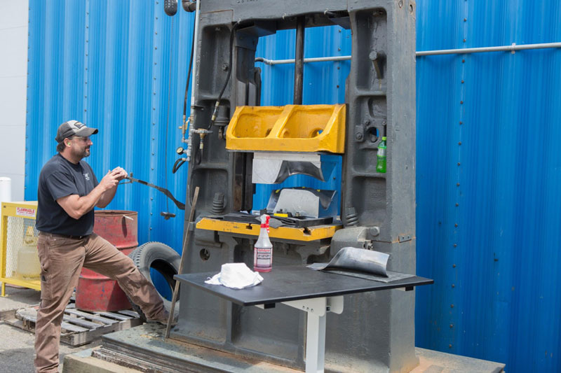
Kris stamps rear stabilizer fairing pieces.