Texas Flying Legend Museum’s
by Chuck Cravens

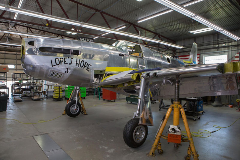
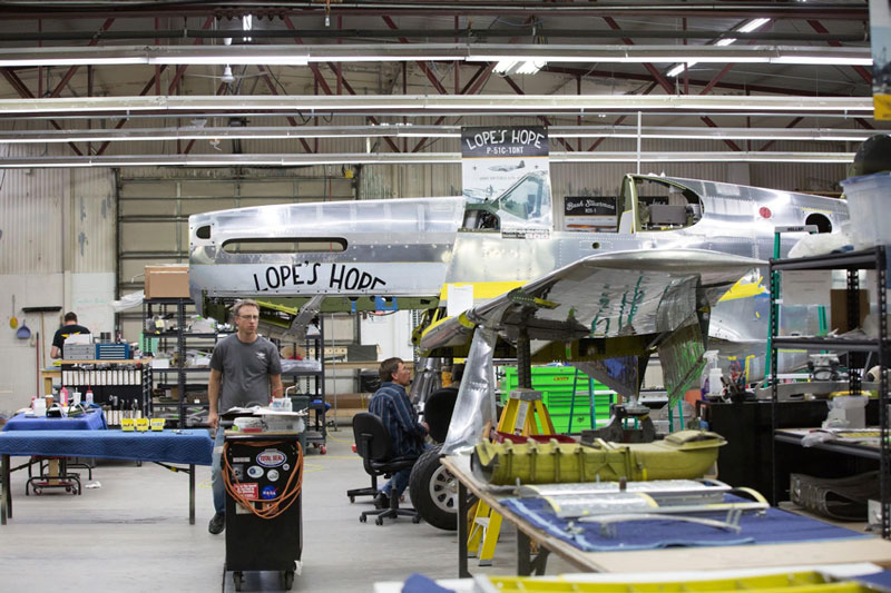
Lope’s Hope 3rd sits ready for a visit by Dr. Donald Lopez, Jr. & Laura Lopez
Update…
The restoration is nearing completion as you will see in this month’s update. Many more visually interesting operations happen near the end, so this time there are many photos. We will begin with a visit by some special folks who made a trip to see Lope’s Hope 3rd andmeet the restoration team and owners of this P-51C.
Distinguished Visitors
Donald Lopez’s son and granddaughter, Dr. Donald Lopez, Jr. and Laura Lopez, came all the way to AirCorps in Bemidji to take a look at the P-51C being restored in Donald’s honor.
They were able to see another P-51, a “D” model fly when Texas Flying Legends’ Bruce Eames and Warren Pietsch departed after the visit.

(L-R)Warren Pietsch of Texas Flying Legends Museum, Laura Lopez, Bruce Eames of Texas Flying Legends Museum, and Dr. Donald Lopez Jr. together in front of Lope’s Hope 3rd in the AirCorps restoration shop.
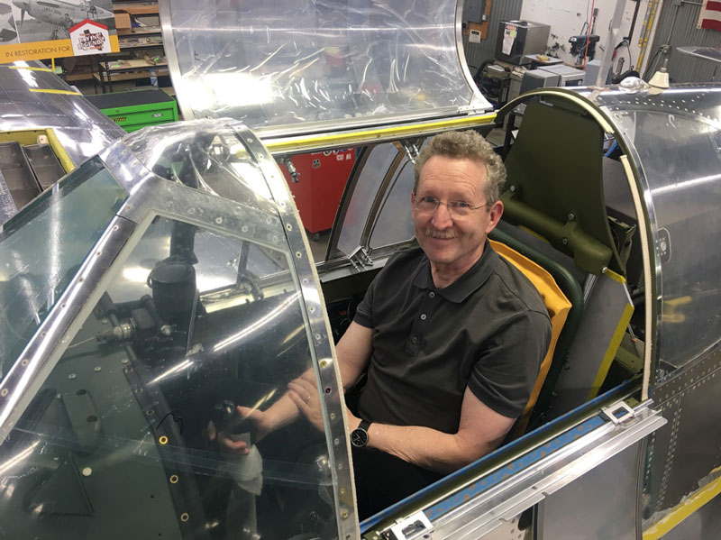
Dr. Lopez looks right at home in the P-51C!
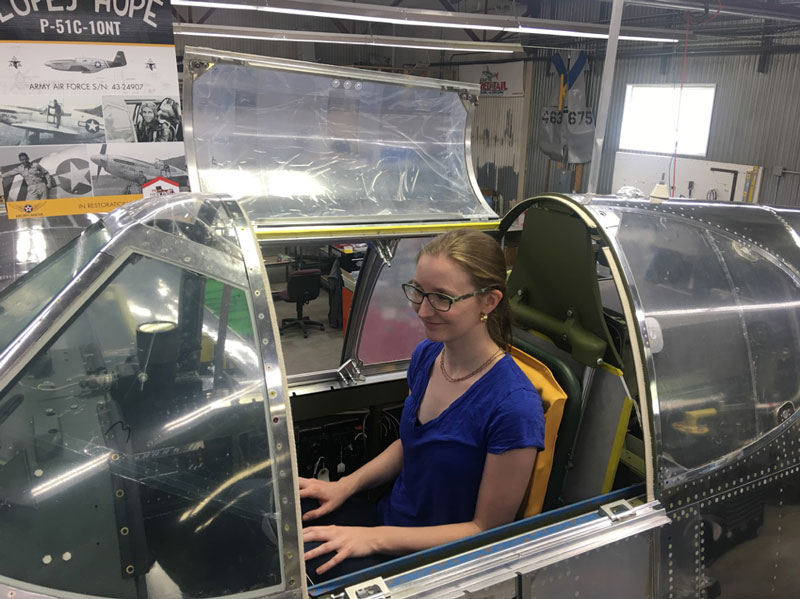
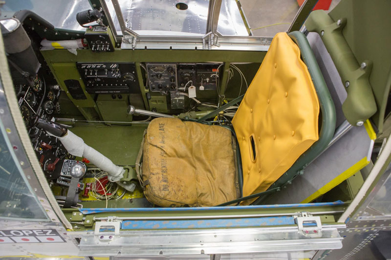
Laura experiences what her grandfather felt and saw in the cockpit of Lope’s Hope 3rd.
Cockpit
A great deal of finish work and equipment installation in the cockpit was accomplished this month.
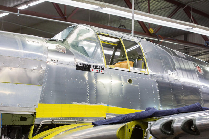
Exterior shot shows the pilot name and victory markings.
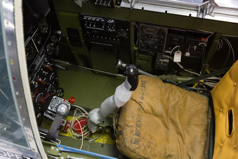
In this view of the seat and stick from above, you can see that there is still some wiring being done.
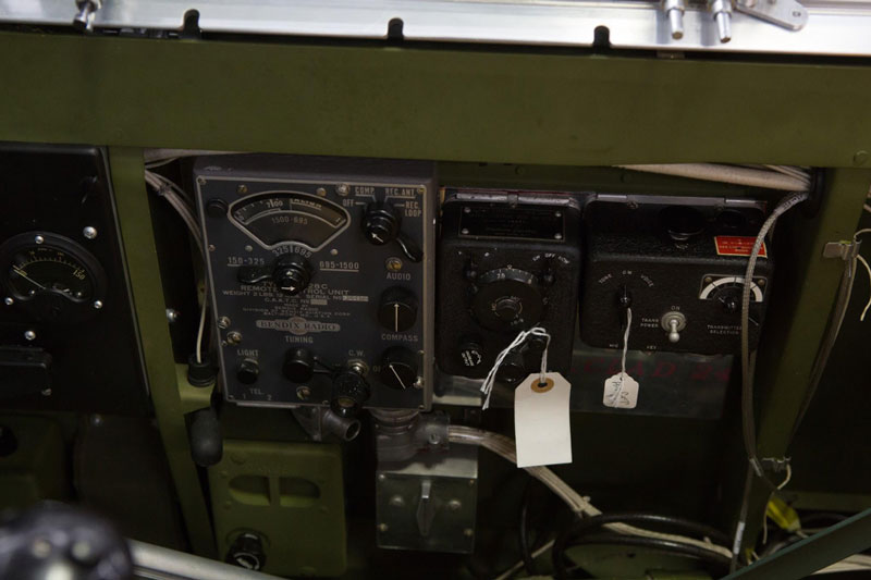
Lope’s Hope has a CBI-specific radio package. The three electronic boxes house, l-r, the MN-26 radio compass controller, the SCR 274 communications receiver, and transmitter.

The three electronic boxes house, l-r, the MN-26 radio compass controller, the SCR 274 communications receiver, and transmitter.
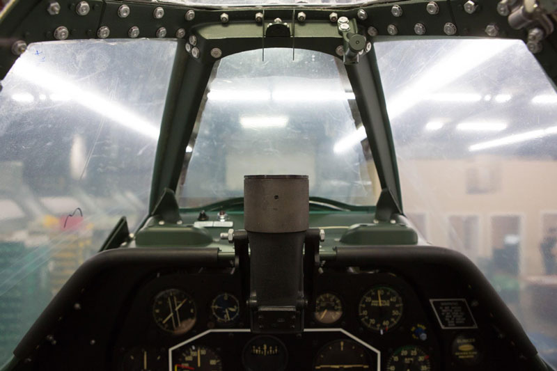
The top of the instrument panel showing the N3B gunsight – the reflector is still to be installed.

The trim console is on the left side of the cockpit.
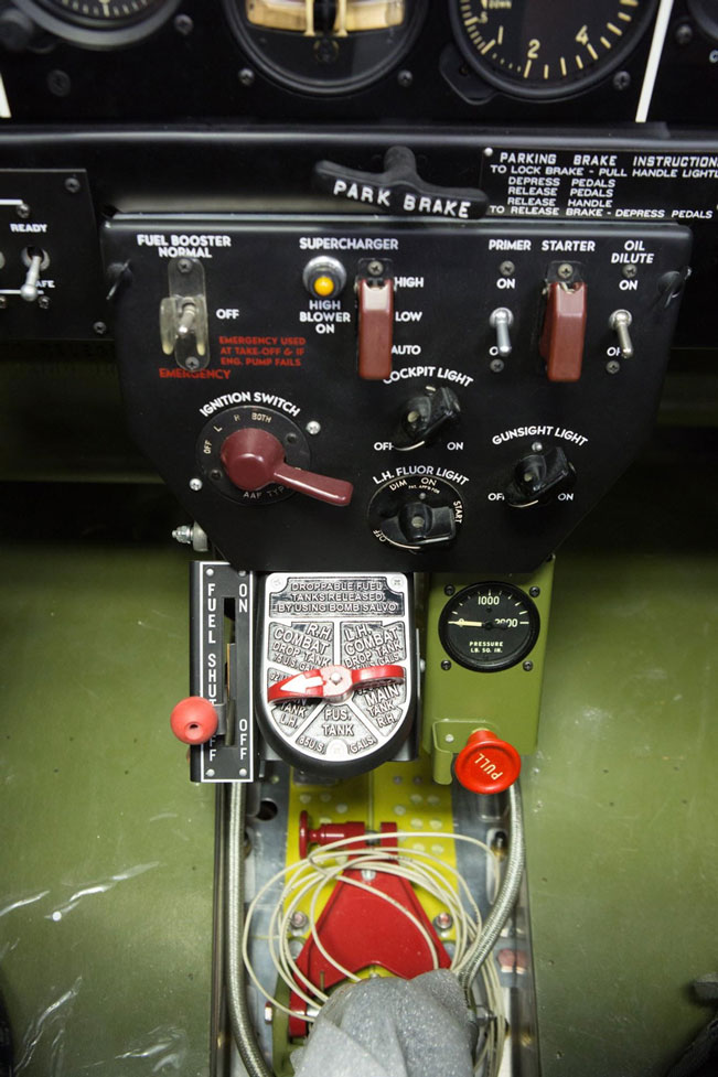
Here we have the pilot’s main switch box.
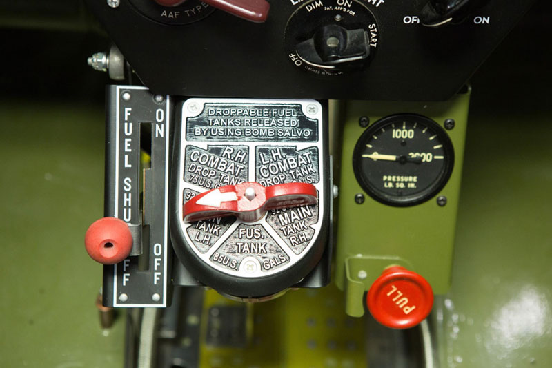
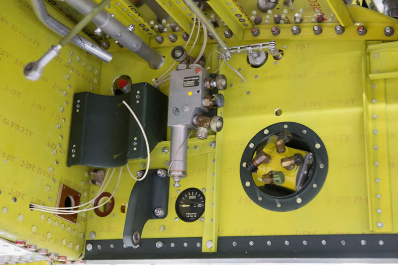
A closer shot shows detail of the fuel shut off, fuel selector, hydraulic pressure gauge, and the red pull knob that would dump hydraulic pressure when pulled.
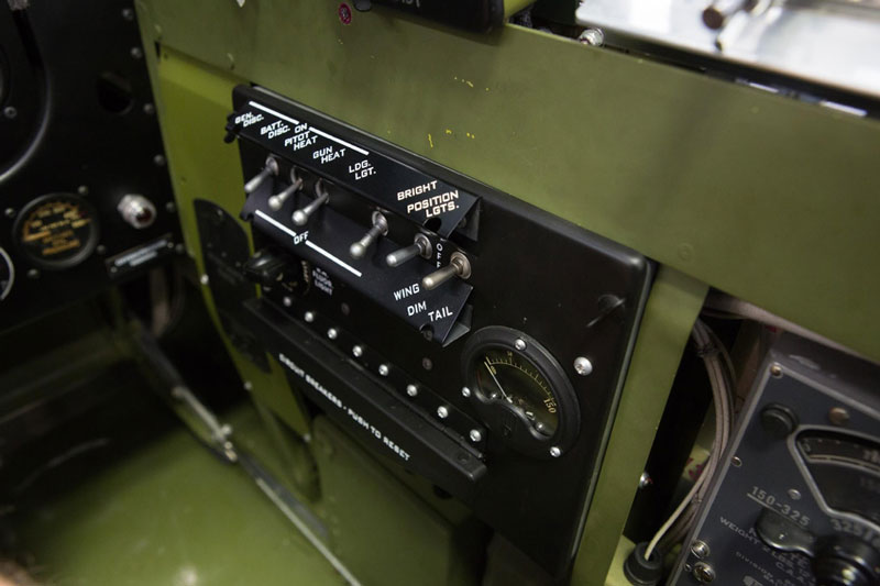
The right side switch box labels show clearly in this photo.
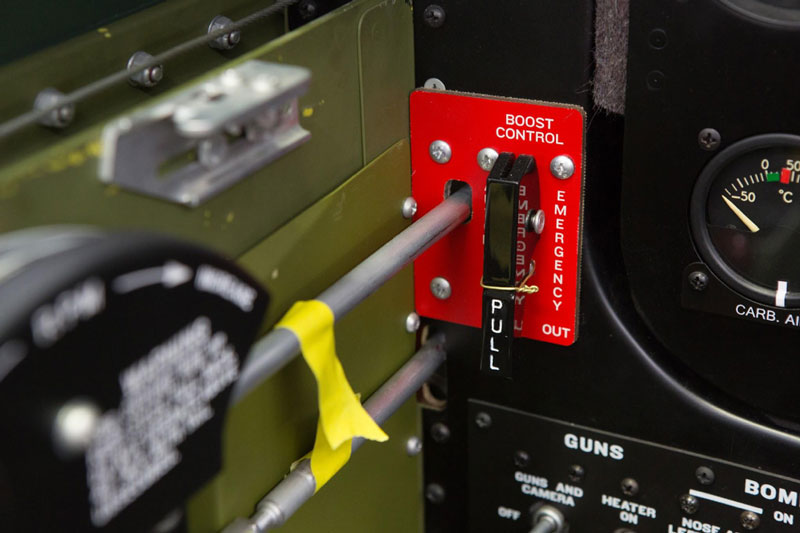
The lever labeled “pull” is the war emergency power control. It is wired down, as they were in WWII, because use of the war emergency boost level would normally call for an engine replacement, so it was intended as a life-saving last resort. The pilot had to pull hard enough to break the wire, so accidental use was prevented.
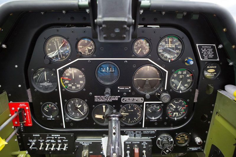
The instrument panel is complete in this view except for the oxygen regulator.
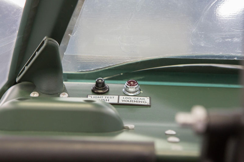
The red light is the landing gear warning light and the push button is used to test the light.
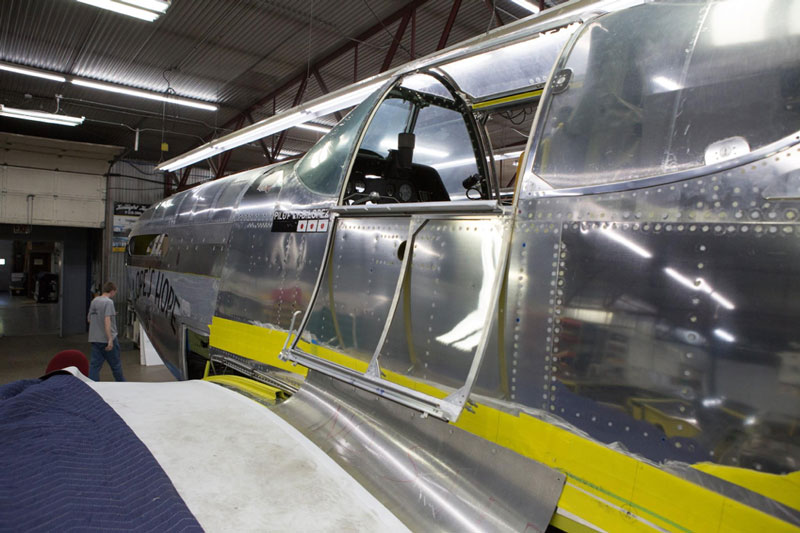
The pilot enters the cockpit from the left. The greenhouse canopy of a P-51C is hinged on the left and top; the ride side is fixed.

Randy is smoothing the tubing bender that he will use for Lope’s Hope’s various tubing runs.
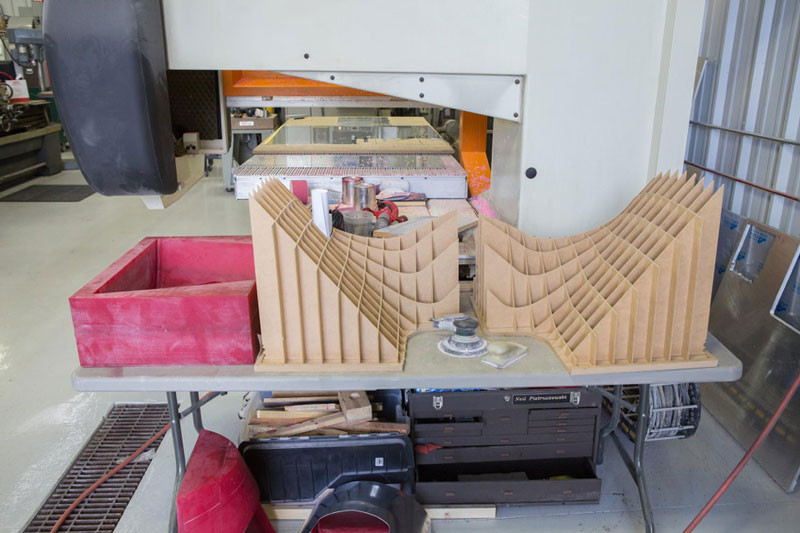
Fairings
Randy Carlson of Carlson Metal Shaping helped us out on the various fillets. He is a specialist in the complex forming of these tightly compound curved pieces.
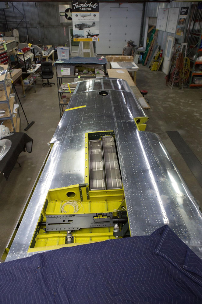
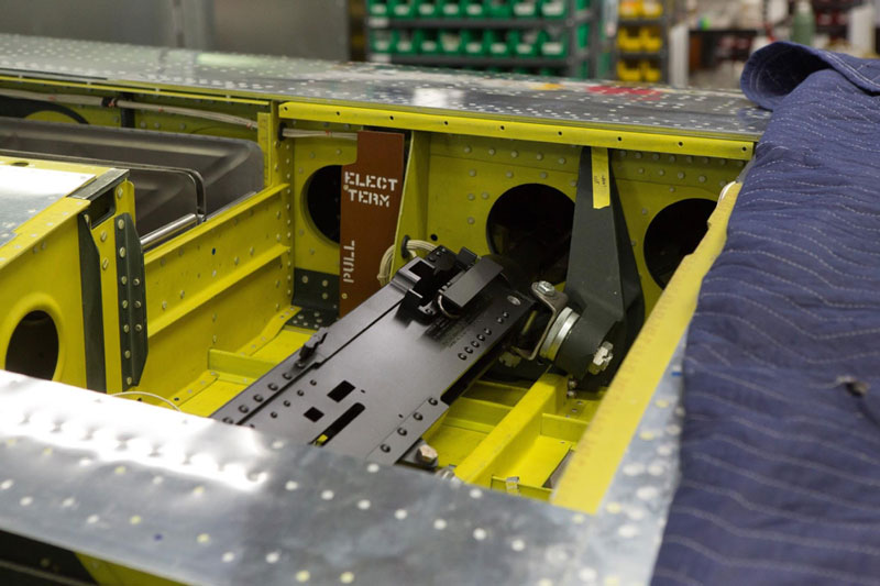
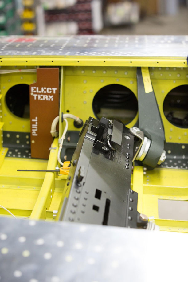
Gun Bays
Without guns it isn’t a fighter, some say, so work on the replica gun installations was an important part of this month’s restoration effort.
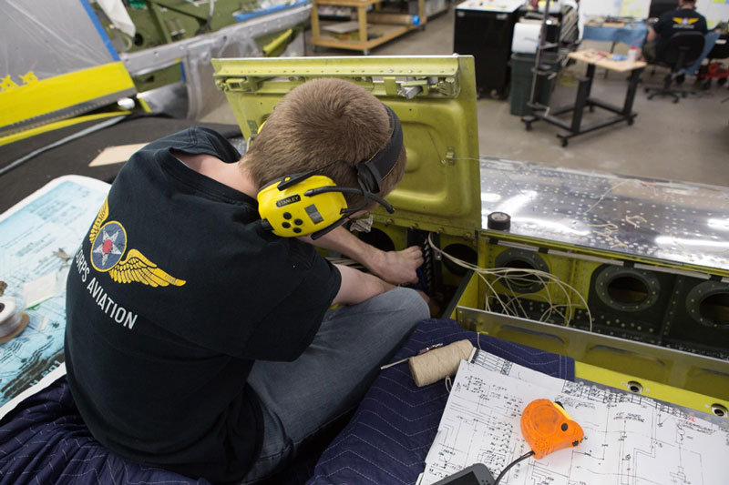
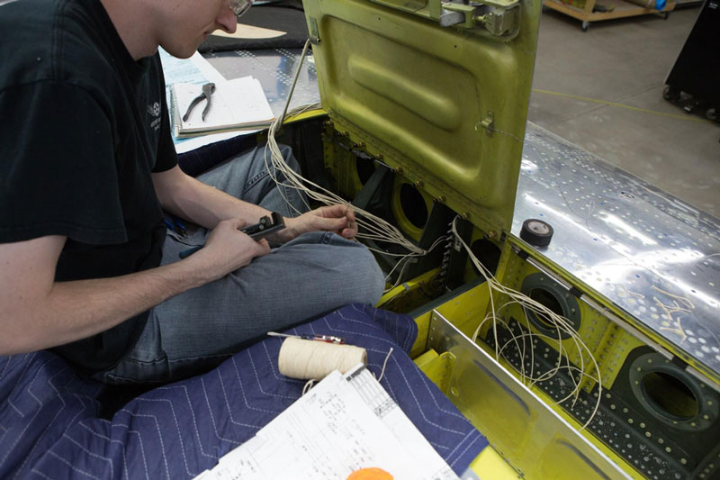
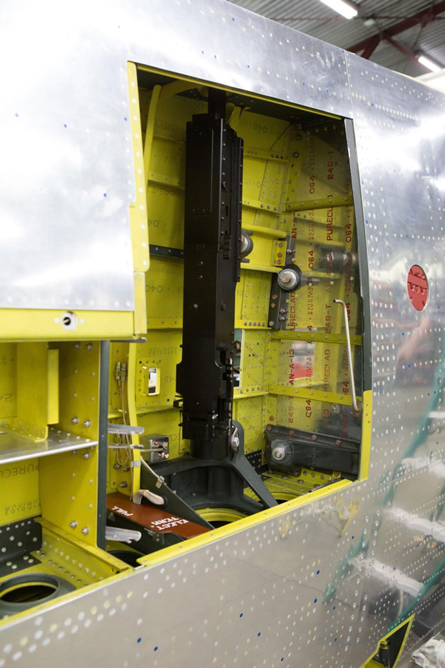
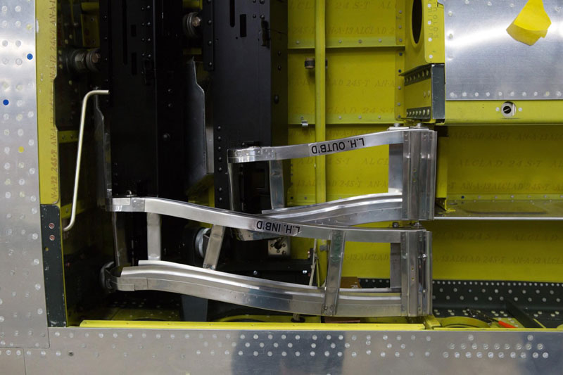
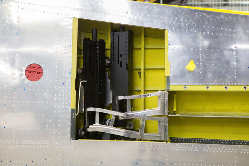
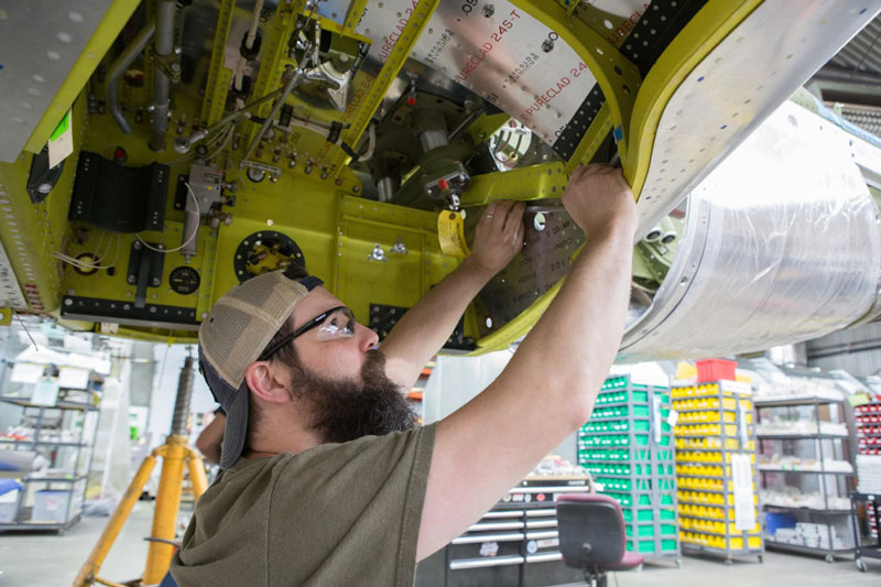
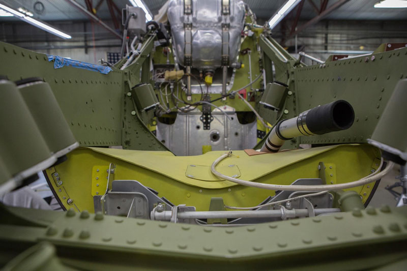
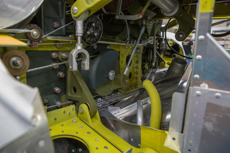
Wheel Wells
Plumbing for hydraulics and running electrical wiring went along with the installation of various system components in the gear wells.
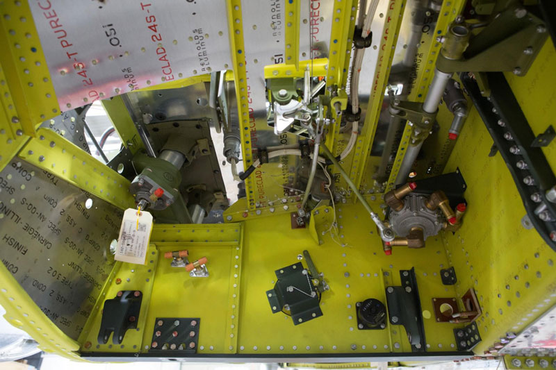
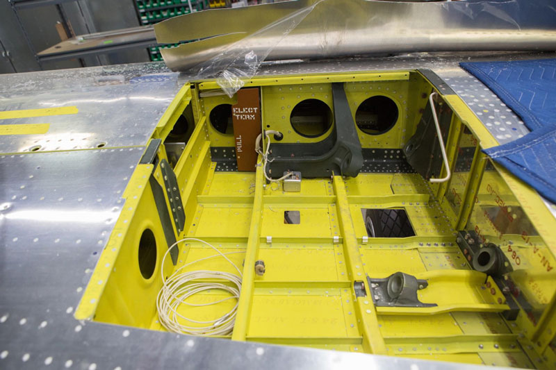
The whole wheel well shows clearly in this photo.
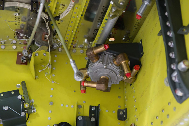
The fuel selector goes inside the wheel well. Thelower elbow is an outlet that delivers fuel to the engine. The other five are inlets from 2 wing tanks, 2 drop tanks, and the fuselage tank.
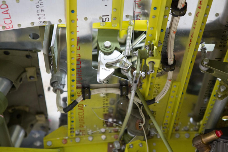
The hook-like part is the main gear uplock latch.

This is one of the main gear hydraulic actuators mounted on the front of the forward spar.

The gear actuator in the other wing has been hooked up to its hydraulic lines.
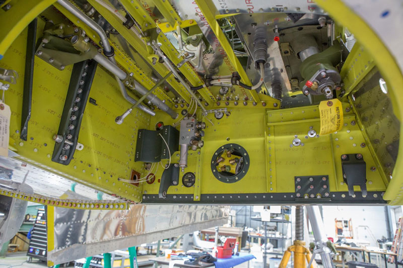
Here we have a good view of most of the wheel well. The tagged part is the gear door hydraulic actuator.
The natural metal part with the black tag is the hydraulic valve for the landing gear.
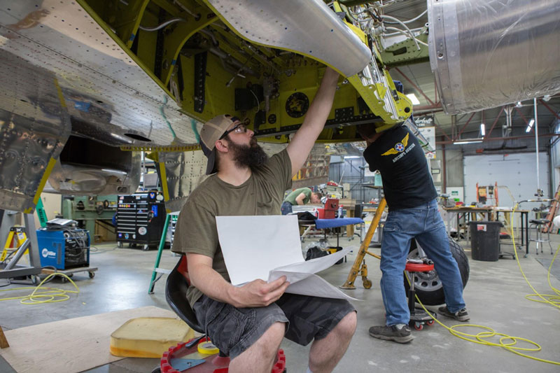
Randy checks the engineering drawings as he looks over gear well installations.
Randy installs a drop tank pressurization line.
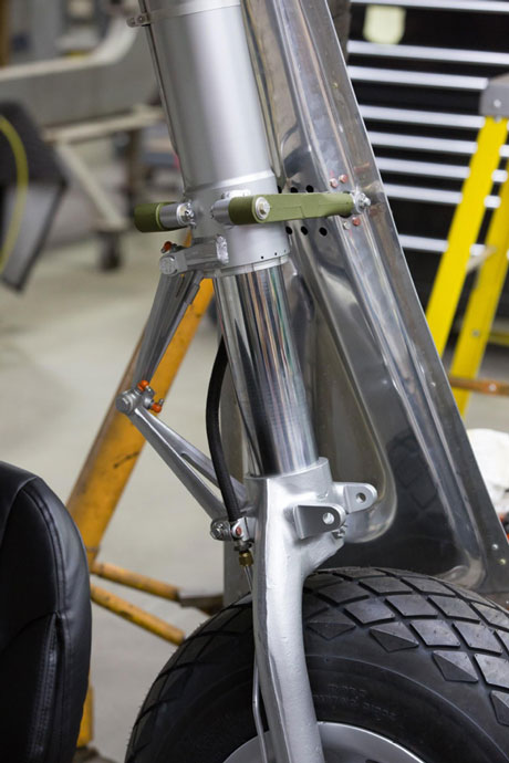
The main gear scissors and fork show up well in this close up.

The hydraulic accumulator stores pressurized hydraulic fluid for the retract system.
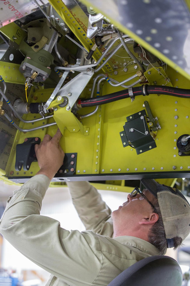
Robb is installing the bracket for the fuel shut off linkage.
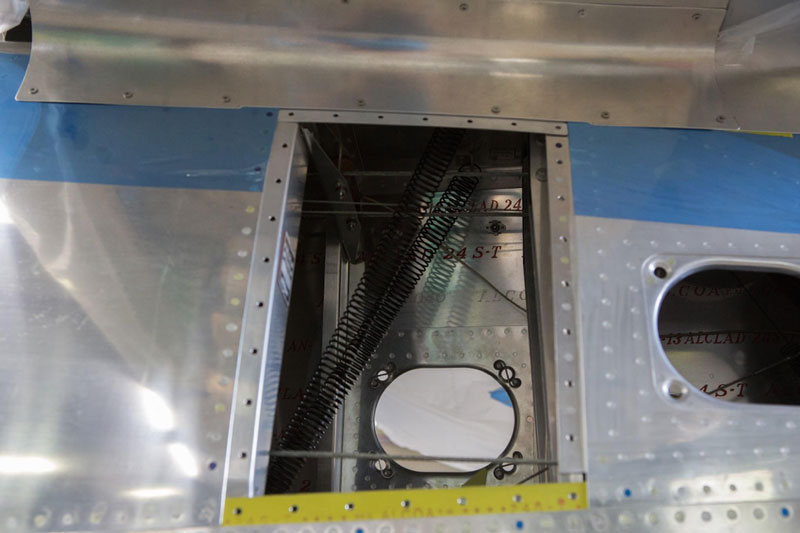
These tailwheel springs hold the tail wheel straight as it retracts.
Firewall Forward
The oil tank is on the firewall and the engine mount assemblies support the “smile”, lower rear cowl section, and the air cleaner boxes.
A front view of the engine mount area shows both the forward and rear engine mountswith their rubber inserts.
Control Systems
The pulley near the middle of the image is the aileron control pulley for the left wing.

A tighter view shows details of the linkage between the control stick torque tube and the aileron pulleys.
The Engine Runs!
Out at the hangar, the V-1650-7 Merlin has been mounted on a truck and test run. This truck belongs to Pat Harker and this is the first time we have had the luxury of running the engine before installing it permanently in a P-51.

The V-1650-7 on a truck from the front.
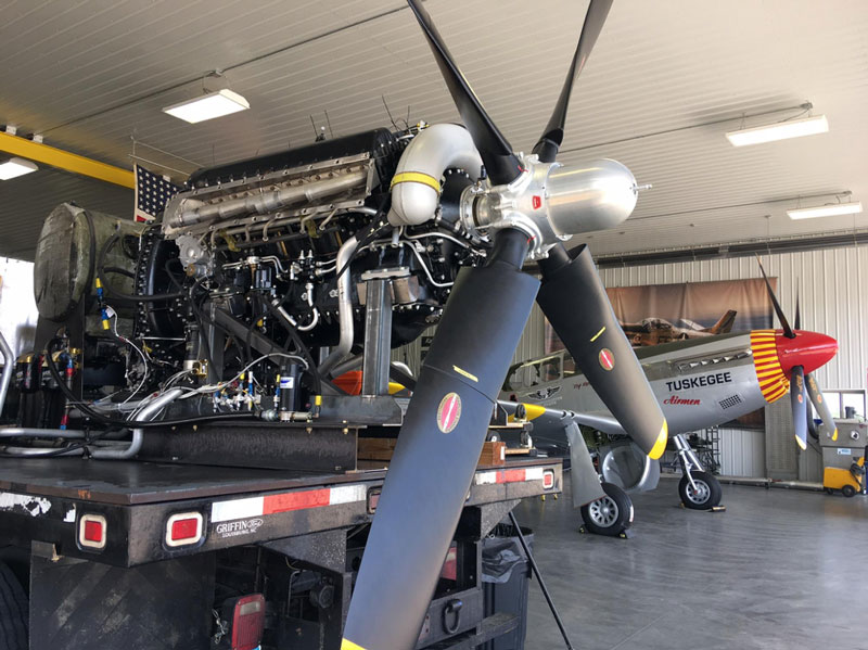
Shortly after the picture, the engine ran beautifully.
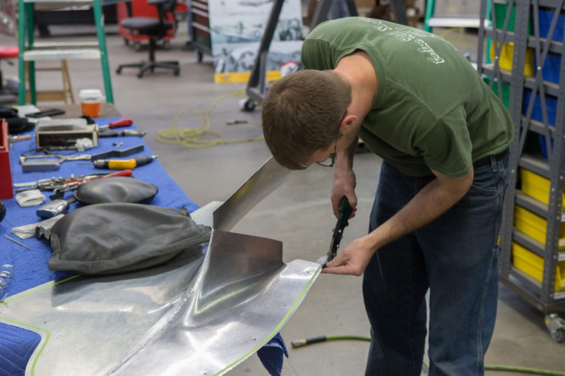
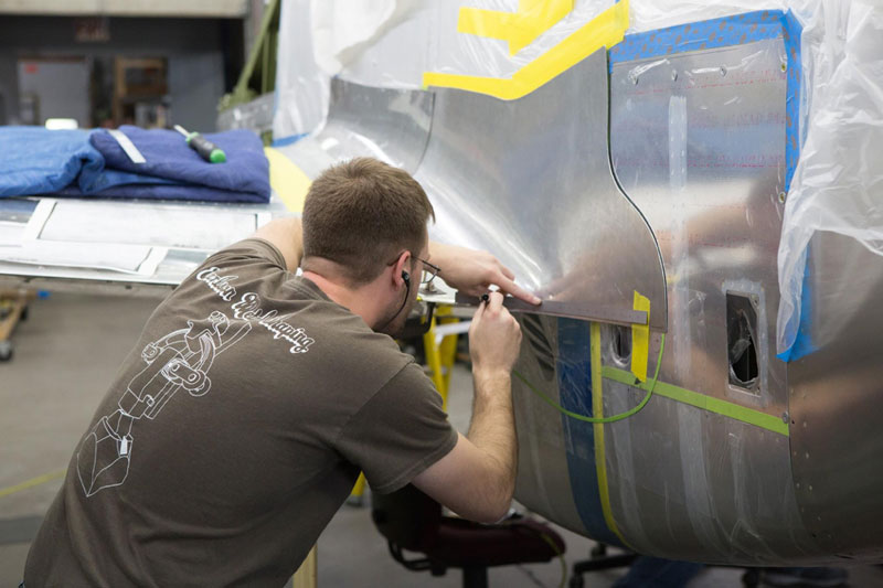
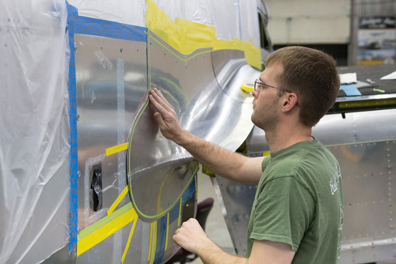
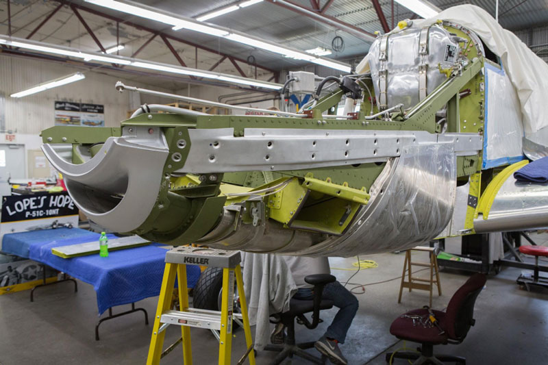
Paint
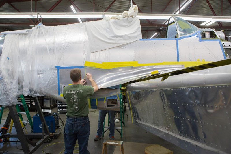
One of the last steps before sending the fuselage and wing out to our hangar for final assembly is the paint process.
Before painting, the wing and fuselage will need to be separated one more time.

The fuselage has been separated and affixed to a rolling fixture.
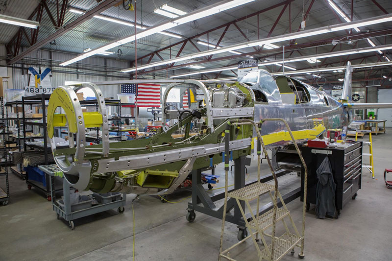
Forward view of the fuselage on the rolling fixture.
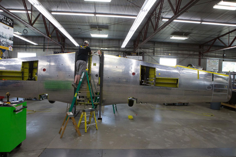
The wing also has a rolling fixture so it can easily be moved into the paint booth.
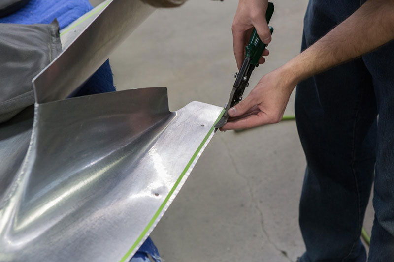
More sanding to get the wings ready for their silver paint is evident in this image.
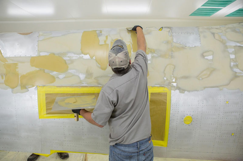
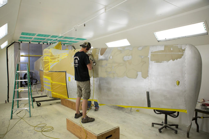
“Aerodynamic Smoothing Compound” being applied by Robb. It was used to maintain the smooth surface of the laminar flow airfoil by filling in rivets and other irregularities. Laminar flow was never completely accomplished on the P-51, despite the compound and painting that followed.
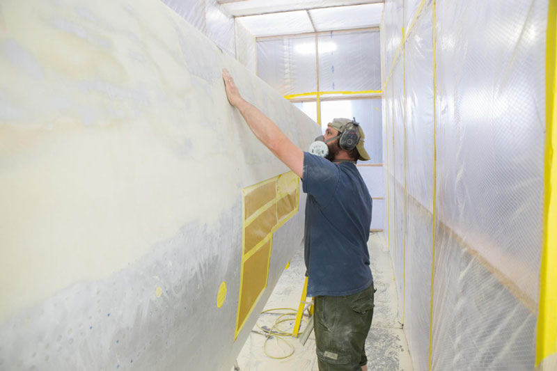
A great deal of sanding, that Randy is doing here, is required.