Texas Flying Legends
by Chuck Cravens

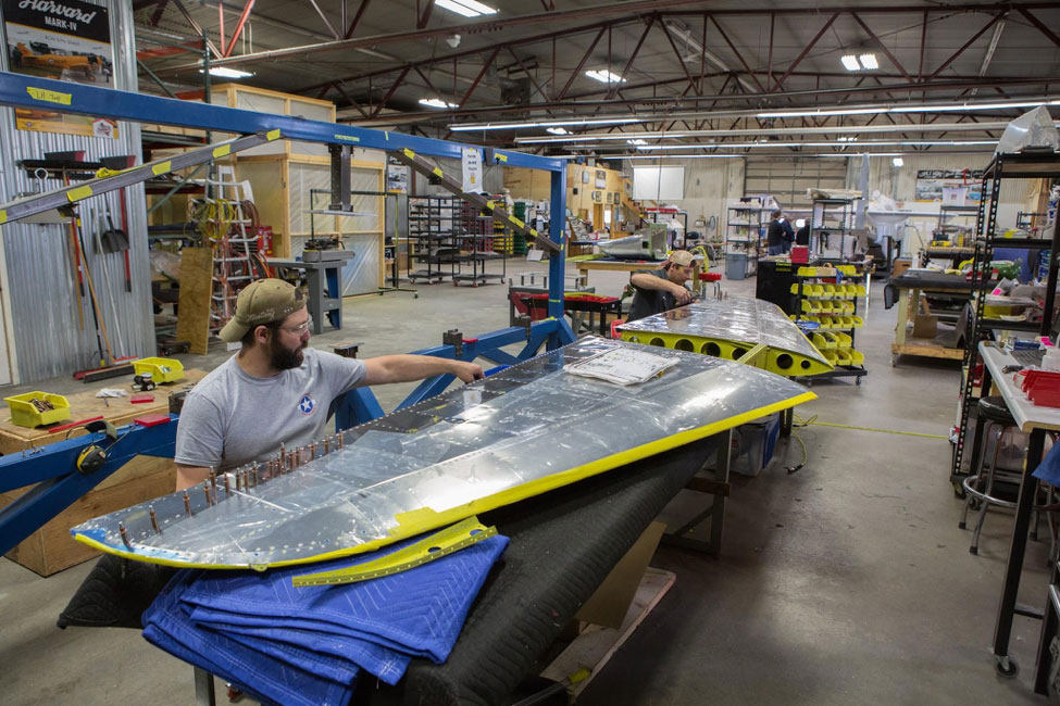
Randy works on some of the last rivet placements in the skin.
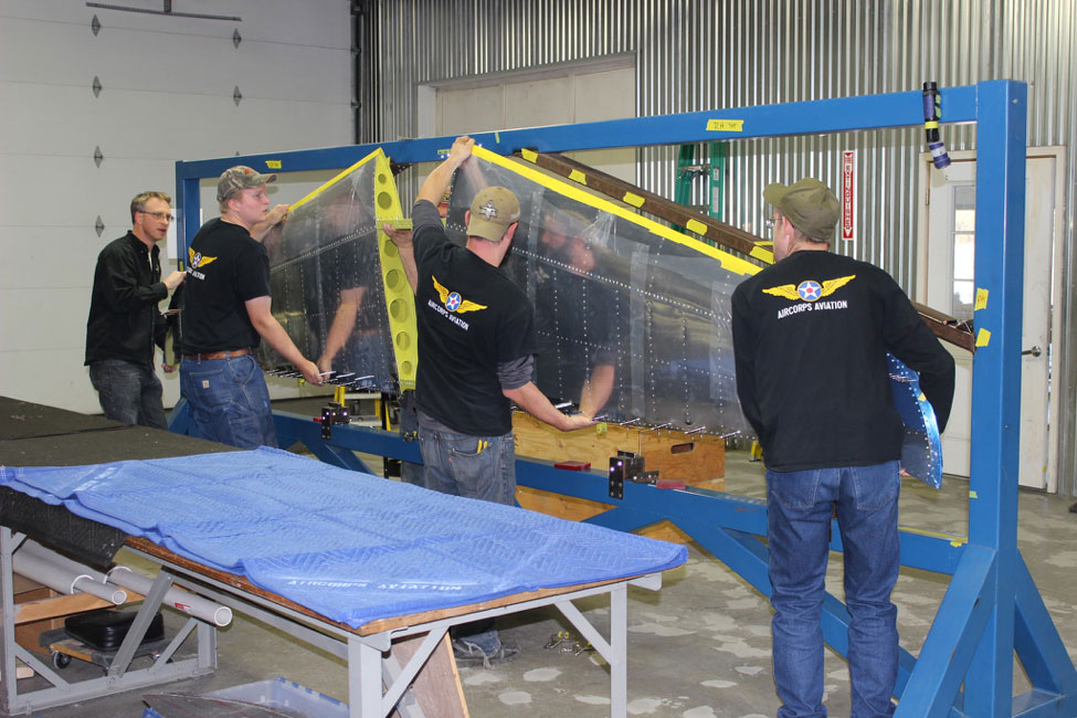
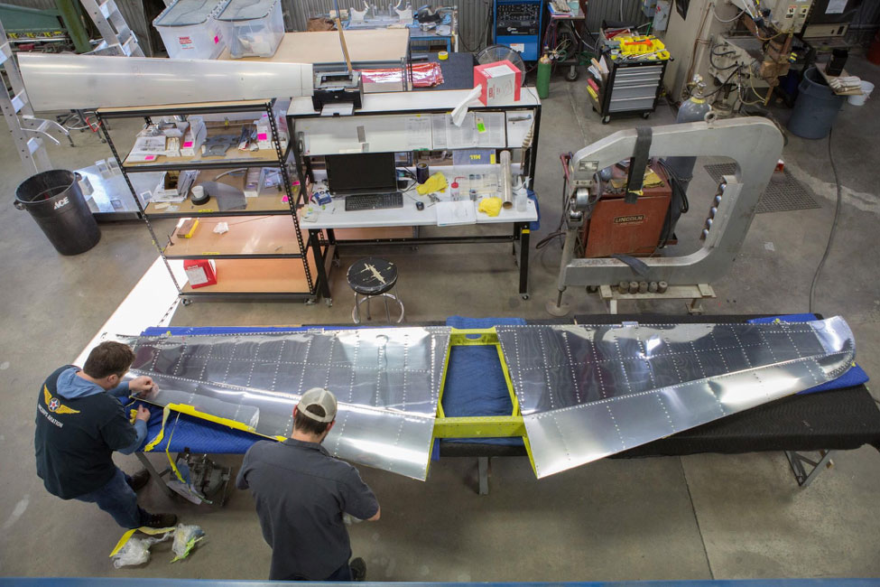
Ryan, Dalton, Randy, and Sam begin the move of the horizontal from the fixture to the bench.
Update on the P-47
Last month we looked into the assembly of the horizontal stabilizer. This month the horizontal, the first large assembly of the project, came out of its fixture. The restoration continued with the start of the disassembly of the fuselage.
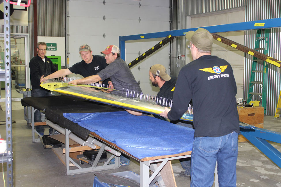
The guys are carefully setting it down on the padded bench.
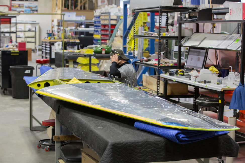
The horizontal is safe on the bench, ready for some final work.
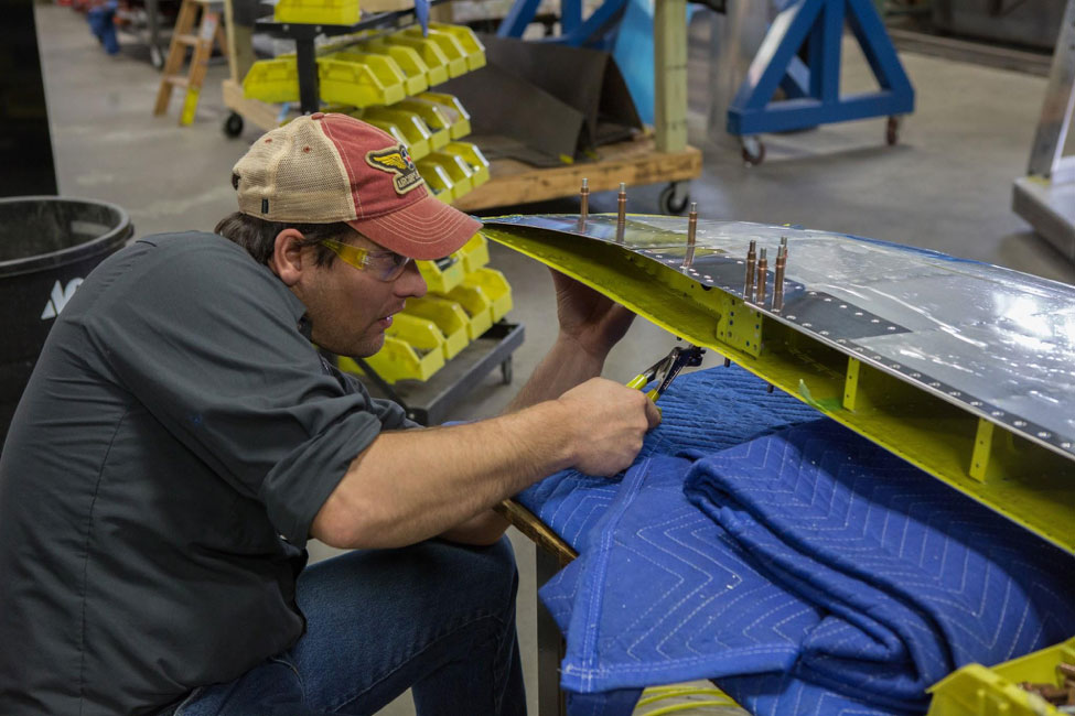
Brent takes out some Clecoes in preparation for replacing them withspecially made rivets that have a 115 degree head angle.
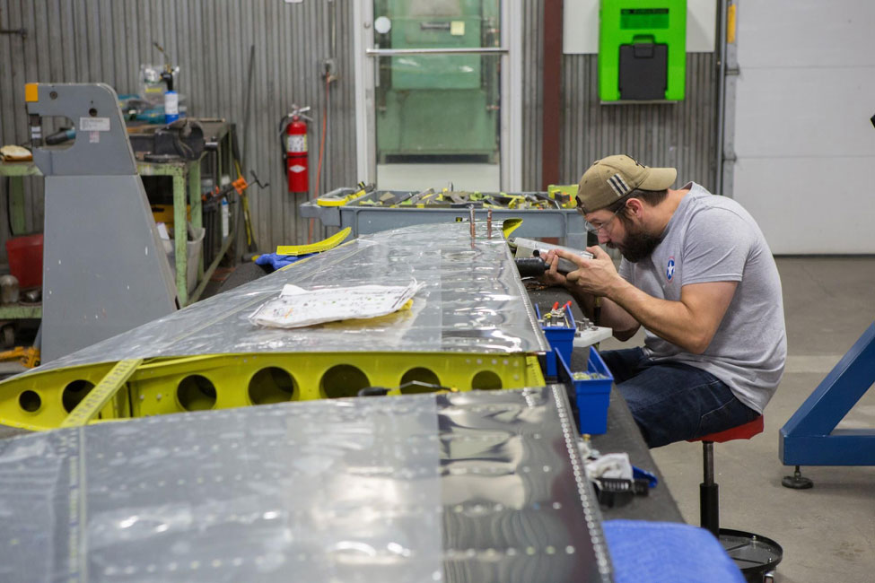
Randy using a rivet squeezer to get some of the last rivets into tight quarters on the stabilizer.
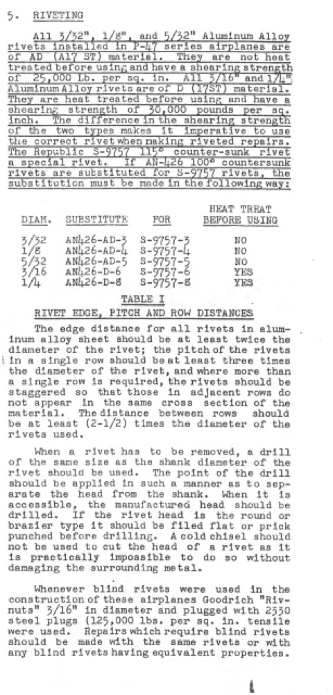
Special AN Rivet Angle
Republic used a wider head angle than the standard 100 degree AN rivet angle. The reason this was done was because the wider angle head could be countersunk in thinner Alclad sheetsthan a standard 100 degree rivet.
In places, the Thunderbolt used thinner skin than many WWII fighters, especially toward the tail. They relied on the structure for strength rather than the skin to a greater degree than other manufacturers.
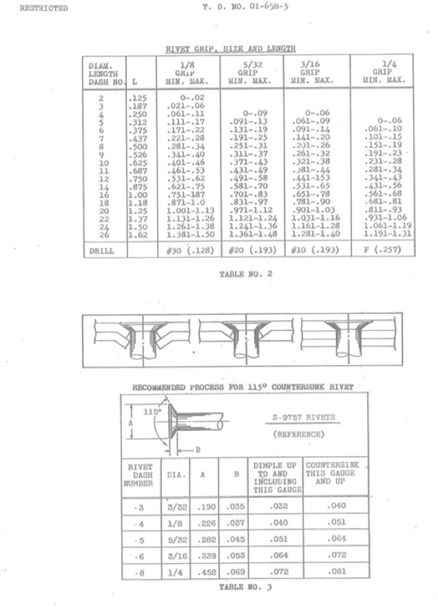
Below are excerpts from theP-47 Series Structural Repair Manual addressing the rivets.
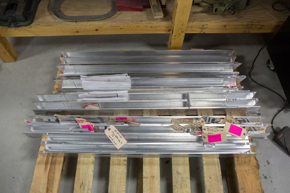 Cross ties that will be connecting the wing fittings through the fuselage.
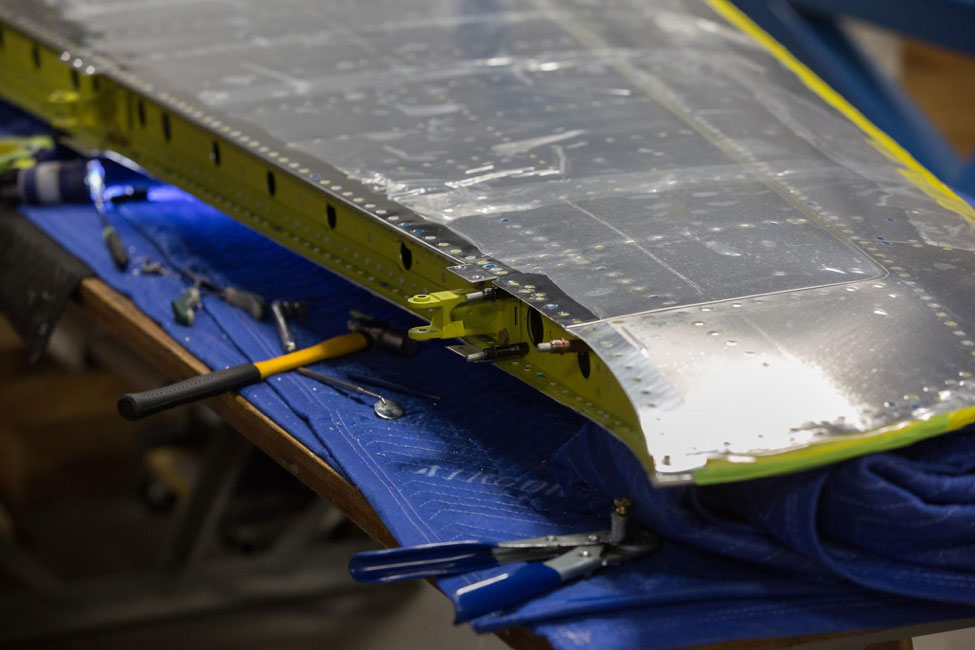
The elevator attachment fitting shows here.
Elevator Attachment
Another link slides over this fitting and is pinned in place. It has a horizontal axis for the elevator hinge itself to attach.
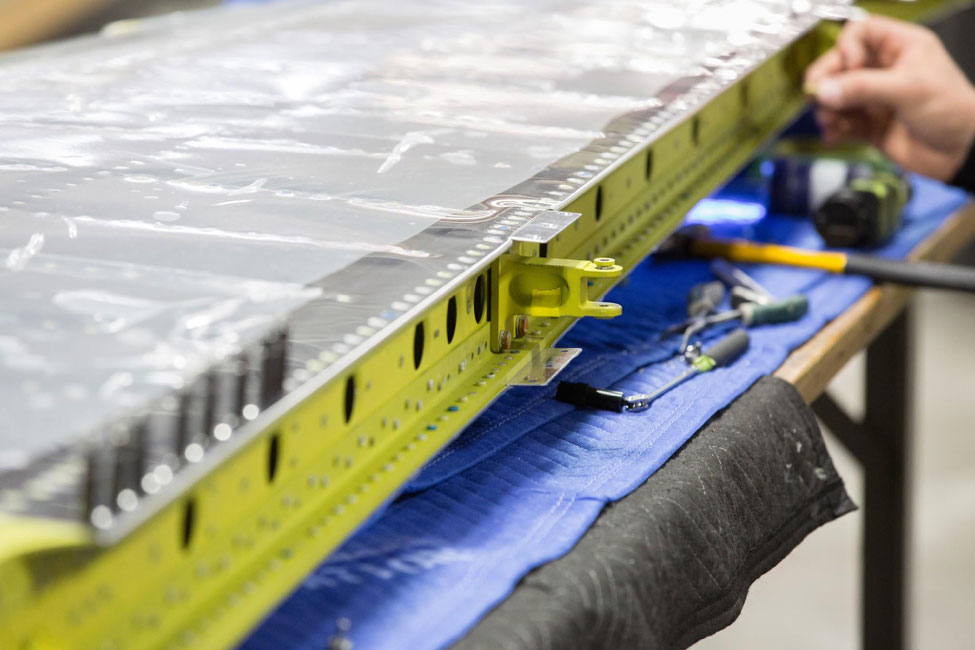
Another view of an elevator fitting, this time it is the inboard one.
Brad and Randy remove protective plastic.
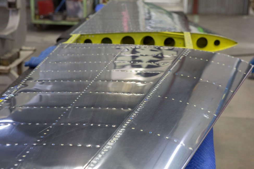
All the rivets are permanently in place in this photo and the horizontal is completely finished.
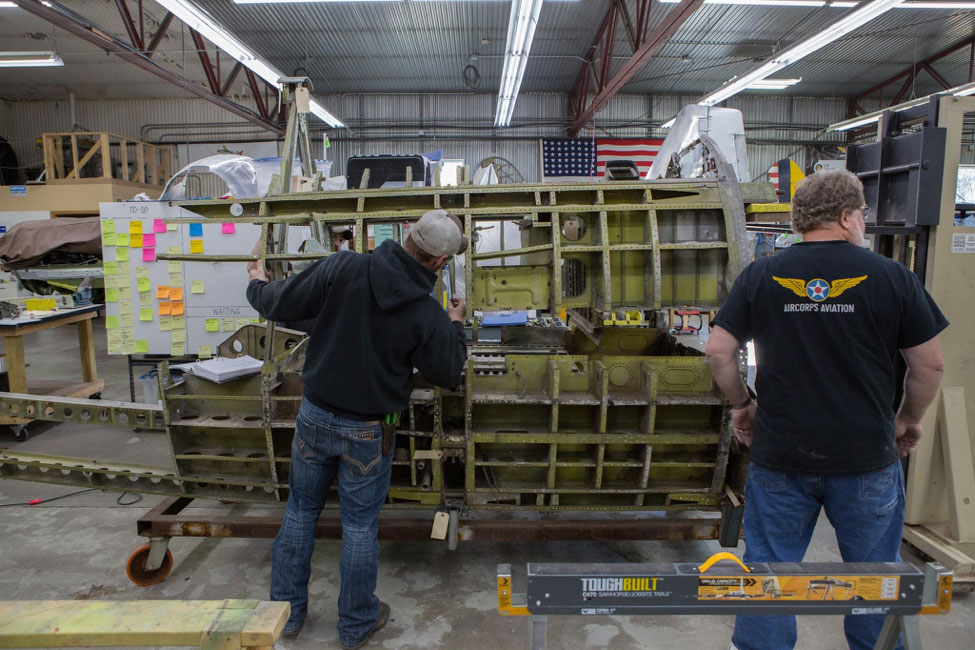
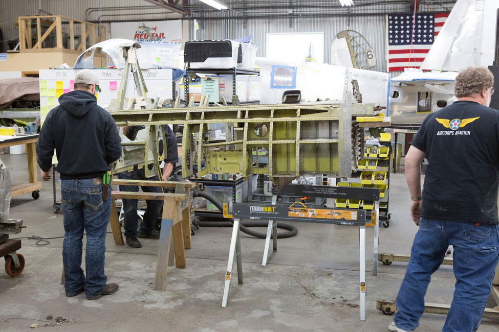
Fuselage
Now that the empennage is progressing well, the time has come to disassemble and evaluate the original fuselage.
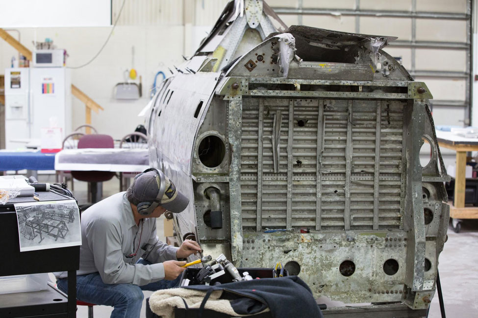
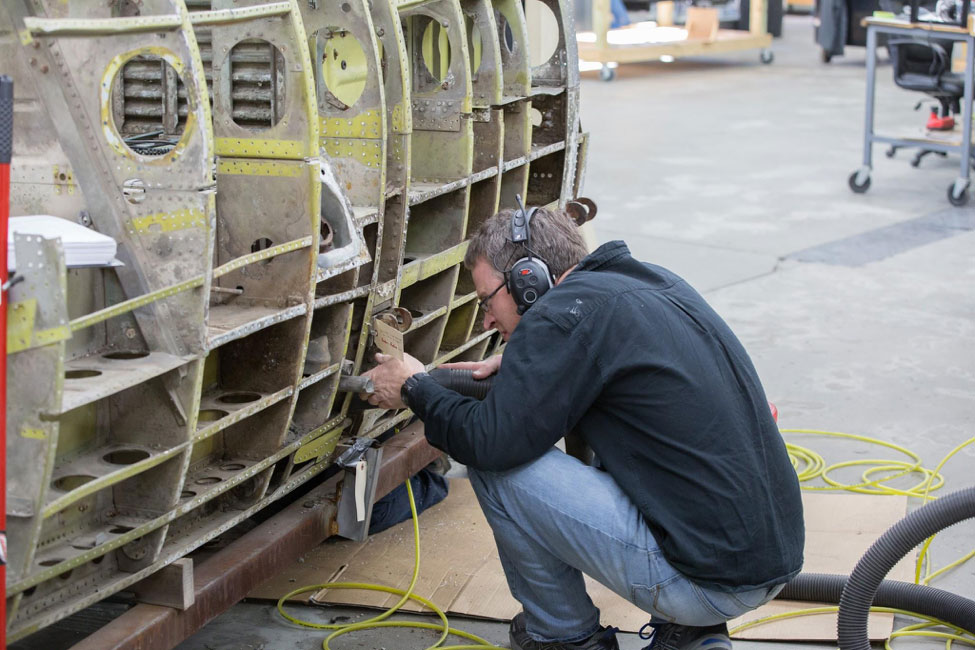
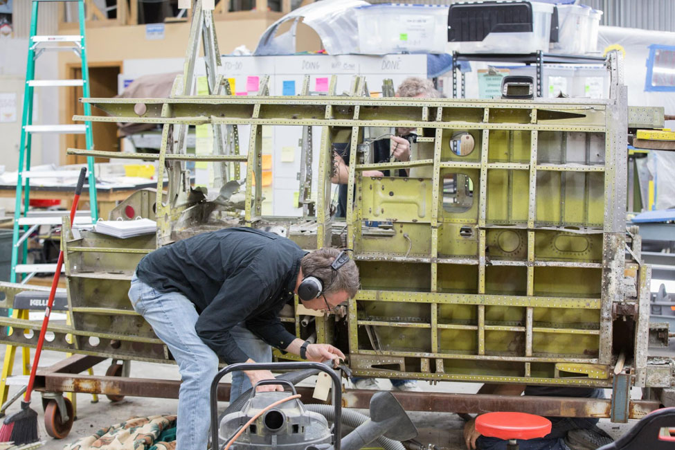
Robb begins the process of removing the fuselage skins.
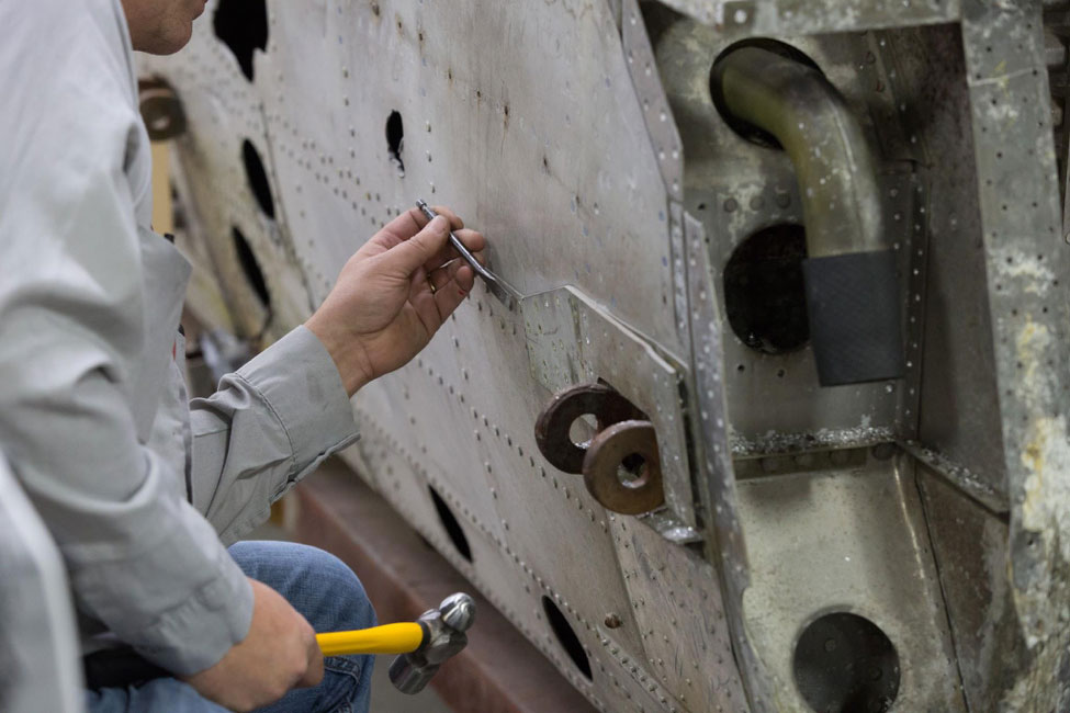
Robb drills a pilot hole into the rivet head and then chisels off the remaining part of the head. This is done so that the hole for the rivet shaft isn’t wallowed out.
Ryan carefully inspects the structure.
Checking a part number tag is part of the process.
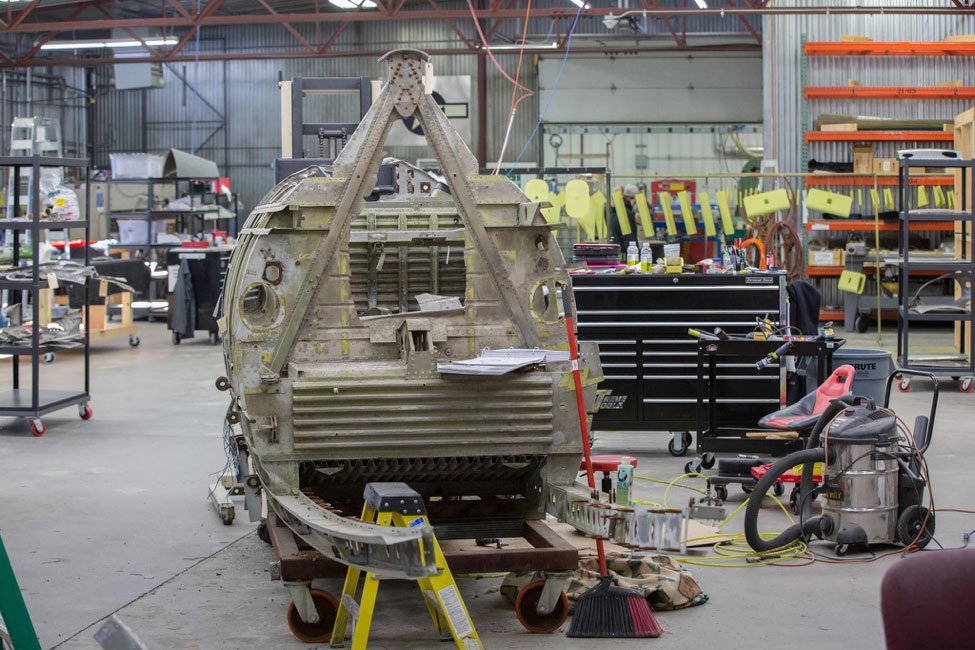
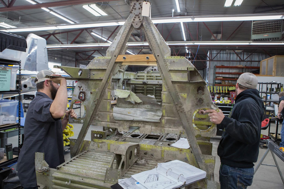
This rear view of the fuselage shows that most of the structure aft of the cockpit has been removed.
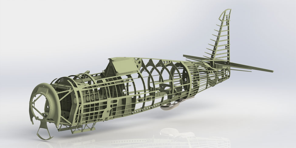
One of Rob McCune’s remarkable renderings helps us to understand the structural layout of the P-47 fuselage.
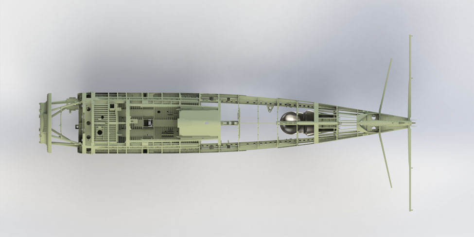
This rendering is a top view of the fuselage structure.
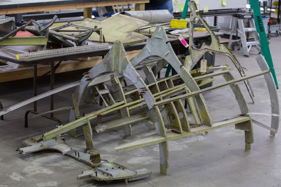
Some of the rear structure we mentioned earlier sits on the floor.
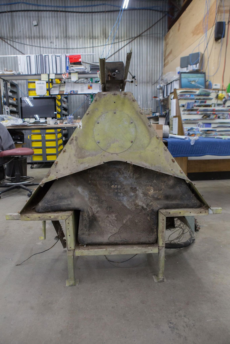
This is the rear side of the “Christmas tree tank”.
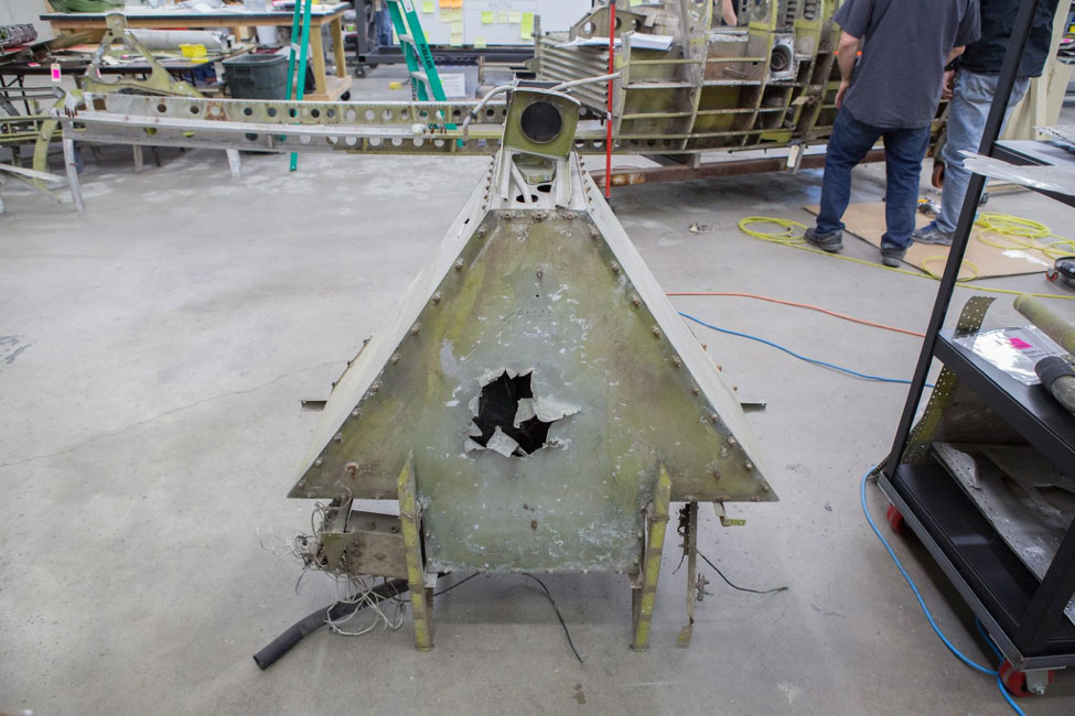
A front side view shows vandalism damage. Thislooks a bit like a shell exit hole but it isn’t; there is no corresponding entry hole.
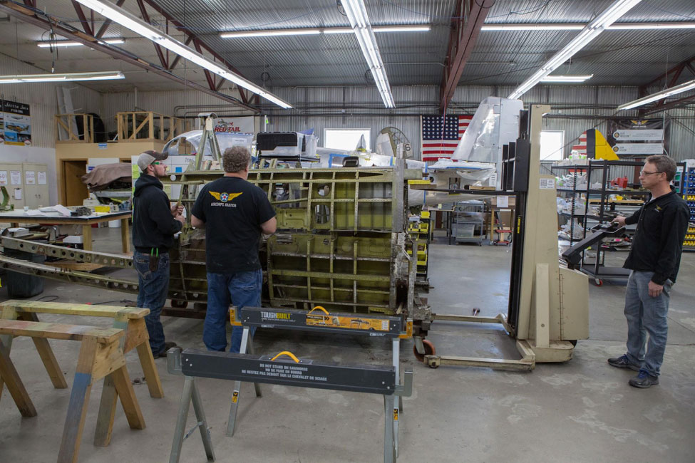
The rivets and bolts holding upper half of the forward fuselage have been drilled out or removed.
The forward upper half comes up. Hunter guides it as Steve looks on.
The guys move the structure carefully.
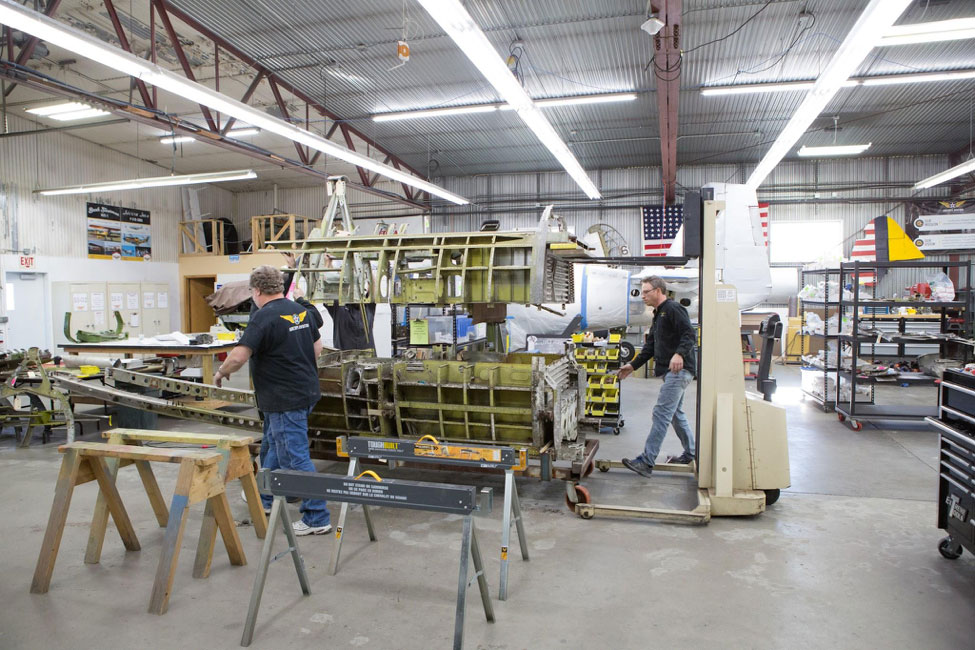
A fork lift helps in this shot.
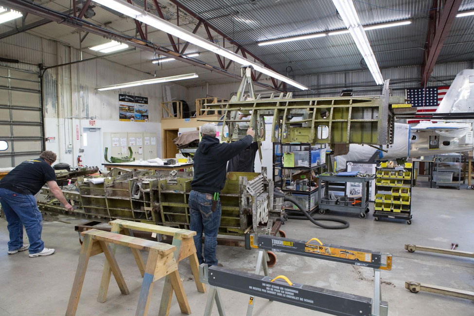
The upper structure is being moved to its ownsupports, separate from the lower section.
Down it comes onto saw horses for now.